8
8
8-24
8-24
Service Mode > Details of Service Mode > #SCAN > READER
Service Mode > Details of Service Mode > #SCAN > READER
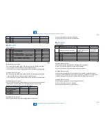
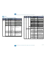
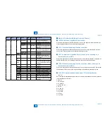
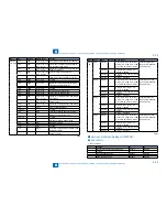
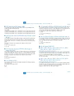
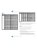
(#SCAN> READER> FUNCTION> CCD> DF-WLVL3)
ADF white level adjustment (platen board cover scan).
MEMO:
Scan a blank sheet on the platen and adjust the white level.
(#SCAN> READER> FUNCTION> CCD> DF-WLVL4)
ADF white level adjustment (DF scan).
MEMO:
Scan a blank sheet in stream reading mode and adjust the white level.
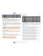
(#SCAN> READER> FUNCTION> CLEAR> R-CON)
Clearing of the backup area for the reader in the main controller.
Clear the backup area for the reader in the main controller.
(#SCAN> READER> FUNCTION> MISC-R> SCANLAMP)
The test checks to see if the scanning lamp is on or not.
Execute the when replacing the scanning lamp.
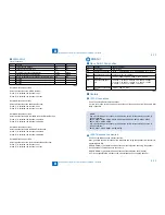
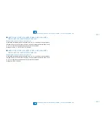
(#SCAN> READER> OPTION> BODY> SENS-CNF)
Setting of the document detection sensor placement
The setting of document detection size is selected in accordance with the document sensor
placement.
0: AB type
1: Inch type
2: A type
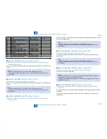
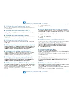
(#SCAN> READER> OPTION> BODY> DFDST-L1)
Dirt detection level adjustment (between documents) during ADF use.
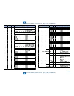
(#SCAN> READER> OPTION> BODY> DFDST-L2)
Dirt detection level adjustment (upon job completion) during ADF use.
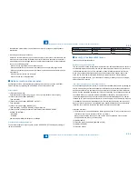
Increase the value when dirt fails to be detected, resulting in black streaks. However, if the
value is increased too much, even small-sized dirt of the kind which does not appear on the
image will also be detected, and the cleaning instruction screen may appear frequently.
●
●
●
●
●
●
●
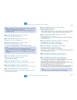
Reduce the value if users complain because the cleaning instruction screen which appears
when dirt is detected is displayed frequently. Conversely, if the value is reduced too much,
black streaks may appear on the images.
When '0' is set, the correction control function used when dirt is detected is canceled.
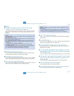
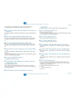
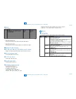
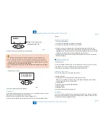
(#SCAN> FEEDER> ADJUST> DOCST)
Adjusting the original stop position for ADF pickup (original tray pickup).
Delivering the original enables the setting. Be sure to press the OK key to deliver the original.
When changing the setting, input the setting on the main station service label.
The larger the value, the smaller the leading edge margin.
(#SCAN> FEEDER> ADJUST> LA-SPEED)
Adjusting the original feeding speed in stream reading.
Use this mode to adjust the original feeding speed in stream reading mode.
The larger the setting, the faster the speed (the image reduced).
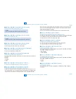
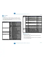
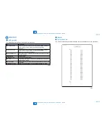
(#SCAN> FEEDER> FUNCTION> MTR-CHK)
Operation check for the ADF motor, etc.
Specify a paper feed mode to check passage of paper by the DF. Select #SCAN> FEEDER>
FUNCTION> FEED-ON to execute this.
0:Feed motor(M1)
1:Pickup motor(M2)
(#SCAN> FEEDER> FUNCTION> FEED-CHK)
Checking the passage of paper for ADF.
Specify a paper feed mode to check passage of paper by the DF. Select #SCAN> FEEDER>
FUNCTION> FEED-ON to execute this.
0:1-sided
1:2-sided
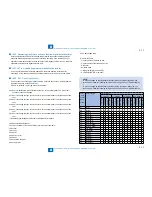
(#SCAN> FEEDER> FUNCTION> FAN-CHK)
Checking the ADF cooling fan.
Specify a fan to perform a fan check. Select #SCAN> FEEDER> FUNCTION> FAN-ON to
execute this.
●
●
●
●
●
Summary of Contents for IMAGERUNNER 2530
Page 1: ...9 8 7 6 5 4 3 2 1 imageRUNNER 2530 2525 2520 Series Service Manual...
Page 4: ...Blank Page...
Page 16: ...1 1 Product Overview Product Overview Product Lineup Feature Specifications Name of Parts...
Page 111: ...3 3 Periodical Service Periodical Service Consumable Parts and Cleaning Parts...
Page 159: ...5 5 Adjustment Adjustment Outline Adjustment when replacing parts Image position adjustment...
Page 166: ...6 6 Troubleshooting Troubleshooting Upgrading Targets and Procedure...
Page 171: ...7 7 Error Code Error Code Overview Error Code Jam Code Alarm Code...
Page 186: ...8 8 Service Mode Service Mode Outline Details of Service Mode...
Page 321: ...Service Tools General Circuit Diagram Appendix...


