8
8
8-26
8-26
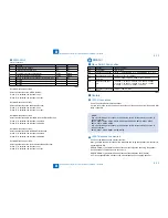
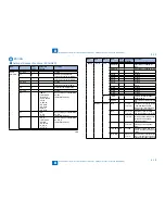
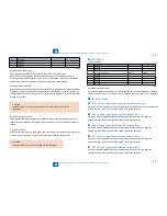
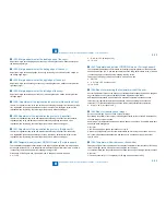
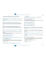
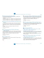
Service Mode > Details of Service Mode > #PRINT > Service Soft Switch Settings (PRINTER)
Service Mode > Details of Service Mode > #PRINT > Service Soft Switch Settings (PRINTER)
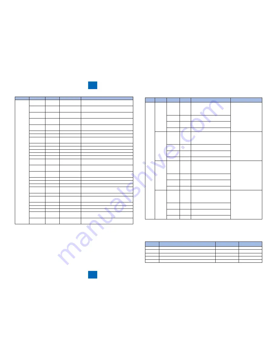
Item
No.
Default
Setting range
Function
NUMERIC
141:
100
'-128 to 127, one
unit = 0.1 mm
Left-end registration adjustment (double-
sided large)
142:
100
'-128 to 127, one
unit = 0.1 mm
Adjustment of margin at leading edge at
normal speed (230mm/sec)
143:
100
'-128 to 127, one
unit = 0.1 mm
Adjustment of margin at leading edge at half
speed (137mm/sec)
144:
100
'-128 to 127, one
unit = 0.1 mm
Laser trail edge OFF adjustment
145:
1000
'-512 to 511
Adjustment of the magnification to write
image in main scanning direction (A-B)
146:
1000
'-512 to 511
Not used
147:
1000
'-512 to 511
Not used
148:
1000
'-512 to 511
Adjustment of the point to start writing in
main scanning direction (A-B)
149:
1000
'-512 to 511
Not used
150:
1000
'-512 to 511
Not used
151:
100
'-128 to 127
Developing bias offset for DC
152:
100
'-128 to 127
Primary charge offset for DC
153:
100
'-128 to 127
Primary charge offset for AC
154:
100
'-128 to 127, one
unit = 0.1 mm
Adjustment of the registration loop volume
(Thick paper)
155:
100
'-128 to 127, one
unit = 0.1 mm
Adjustment of the registration loop volume
(Special paper)
156:
100
'-128 to 127, one
unit = 0.1 mm
Adjustment of the registration loop volume
(Envelop cassette pickup)
157:
7
0 to 14
Pickup timing adjustment
158:-164:
Not used
165:
0
0 to 3
Fixing auto cleaning frequency setting
166:
7
0 to 14
Temperature adjustment UP/DOWN mode
(Plain paper, manual feed tray)
167: 172:
Not used
173:
7
0 to 14
Temperature adjustment UP/DOWN mode
(2nd page of double-sided printing)
174:
0
0 to 1
Reduction in FCOT
175:-177:
Not used
178:
1
0 to 1
Not used
179:
7
0 to 14
Temperature adjustment UP/DOWN mode
(Envelop/Postcard)
180:
7
0 to 14
Temperature adjustment UP/DOWN mode
(Special mode N)
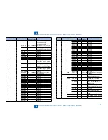
T-8-35
T-8-35
Item1 Item2
Item3
Default Setting range
Function
CST
CAS1
CAS1-U1 0
26: OFI, 27: E-OFI, 37: M-OFI,
36: A-OFI, 24: FLSP, 25: A-FLSP,
30: A-LTRR, 42: FA4, 34: G-LGL
0: default
Cassette 1paper size
group special, standard-
size paper entry
CAS1-U2 0
32: G-LTR-R, 34: G-LGL, 23:
K-LGL-R, 0: default
CAS1-U3 0
22: K-LGL, 31: G-LTR, 29: A-LTR,
0: default
CAS1-U4 0
28: B-OFI, 0: default
CAS2
CAS2-U1 0
26: OFI, 27: E-OFI, 37: M-OFI,
36: A-OFI, 24: FLSP, 25: A-FLSP,
30: A-LTRR, 42: FA4, 34: G-LGL
0: default
Cassette 2 paper size
group special, standard-
size paper entry
CAS2-U2 0
32: G-LTR-R, 34: G-LGL, 23:
K-LGL-R, 0: default
CAS2-U3 0
22: K-LGL, 31: G-LTR, 29: A-LTR,
0: default
CAS2-U4 0
28: B-OFI, 0: default
CAS3
CAS3-U1 0
26: OFI, 27: E-OFI, 37: M-OFI,
36: A-OFI, 24: FLSP, 25: A-FLSP,
30: A-LTRR, 42: FA4, 34: G-LGL
0: default
Cassette 3paper size
group special, standard-
size paper entry
CAS3-U2 0
32: G-LTR-R, 34: G-LGL, 23:
K-LGL-R, 0: default
CAS3-U3 0
22: K-LGL, 31: G-LTR, 29: A-LTR,
0: default
CAS3-U4 0
28: B-OFI, 0: default
CAS4
CAS4-U1 0
26: OFI, 27: E-OFI, 37: M-OFI,
36: A-OFI, 24: FLSP, 25: A-FLSP,
30: A-LTRR, 42: FA4, 34: G-LGL
0: default
Cassette 4 paper size
group special, standard-
size paper entry
CAS4-U2 0
32: G-LTR-R, 34: G-LGL, 23:
K-LGL-R, 0: default
CAS4-U3 0
22: K-LGL, 31: G-LTR, 29: A-LTR,
0: default
CAS4-U4 0
28: B-OFI, 0: default
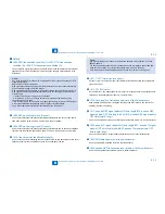
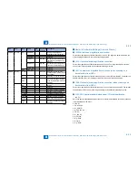
Service Soft Switch Settings (PRINTER)
SSSW-SW14
List of Functions
Bit
Function
1
0
0
Transfer bias pressure reduction mode
Enable
Disable
1
not used
-
-
2
Black belt addition mode
Enable
Disable
3
Post-rotation reduction mode
Enable
Disable
4
Flicker reduction mode
Enable
Disable
■
●
T-8-36
T-8-36
Summary of Contents for IMAGERUNNER 2530
Page 1: ...9 8 7 6 5 4 3 2 1 imageRUNNER 2530 2525 2520 Series Service Manual...
Page 4: ...Blank Page...
Page 16: ...1 1 Product Overview Product Overview Product Lineup Feature Specifications Name of Parts...
Page 111: ...3 3 Periodical Service Periodical Service Consumable Parts and Cleaning Parts...
Page 159: ...5 5 Adjustment Adjustment Outline Adjustment when replacing parts Image position adjustment...
Page 166: ...6 6 Troubleshooting Troubleshooting Upgrading Targets and Procedure...
Page 171: ...7 7 Error Code Error Code Overview Error Code Jam Code Alarm Code...
Page 186: ...8 8 Service Mode Service Mode Outline Details of Service Mode...
Page 321: ...Service Tools General Circuit Diagram Appendix...

