9
9
9-2
9-2
Installation > Making Pre-Checks > Selecting the Site of Installation
Installation > Making Pre-Checks > Selecting the Site of Installation
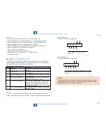
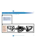
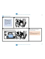
How to check this Installation Procedure
When Using the parts included in the package
A symbol is described on the illustration in the case of using the parts included in the package
of this product.
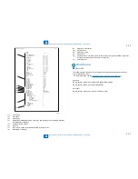
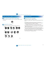
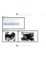
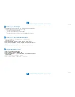
Symbols in the Illustration
The frequently-performed operations are described with symbols in this procedure.
Connector
Disconnect
Screw
Tighten
Remove
Connect
Secure
Free
Harness
Push
Insert
Plug in
Turn on
Sound Check
Check
Visual Check
Claw
Remove
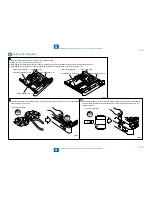
Checking instruction
F-9-1
F-9-1
F-9-2
F-9-2
Making Pre-Checks
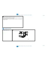
Selecting the Site of Installation
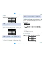
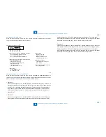
The followings are the condition for installation environment.
It is better to see the planned location of installation before carrying the host machine in the
user site.
1) The host machine can singly connect to the outlet of rated +/-10V, 15A or more.
2) The installation site must be in the following environment. Especially, avoid installing the
machine near the faucet, water boiler, humidifier, or refrigerator.
Operating environment:Temperature: 10.0 to 30.0oC Humidity: 20 to 80%
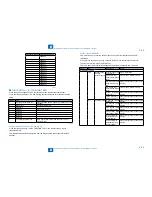
3) Avoid installing the machine near fire, in an area subject to dust or ammonia gas. When
installing the machine in a place exposed to direct rays of the sun, it is recommended that
curtains be hung over the windows.
4) The amount of ozone generated during use of the machine is below the harmful level.
However, if the machine is used for a long time in a poor-ventilated room, ozone may smell.
To keep the work environment comfortable, the room must be well-ventilated properly.
5) None of the machine feet should float. The machine must be held level constantly.
6) The machine must be installed at least 10 cm away from the surrounding walls and there
must be an adequate space for operating the machine.
•
Summary of Contents for IMAGERUNNER 2530
Page 1: ...9 8 7 6 5 4 3 2 1 imageRUNNER 2530 2525 2520 Series Service Manual...
Page 4: ...Blank Page...
Page 16: ...1 1 Product Overview Product Overview Product Lineup Feature Specifications Name of Parts...
Page 111: ...3 3 Periodical Service Periodical Service Consumable Parts and Cleaning Parts...
Page 159: ...5 5 Adjustment Adjustment Outline Adjustment when replacing parts Image position adjustment...
Page 166: ...6 6 Troubleshooting Troubleshooting Upgrading Targets and Procedure...
Page 171: ...7 7 Error Code Error Code Overview Error Code Jam Code Alarm Code...
Page 186: ...8 8 Service Mode Service Mode Outline Details of Service Mode...
Page 321: ...Service Tools General Circuit Diagram Appendix...

