9
9
9-68
9-68
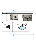
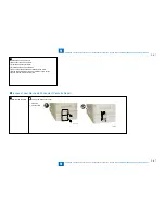
Installation > Cassette Heater Unit 37 > Installation Procedure > In case of Host Machine(250 Sheets of Cassette Model)
Installation > Cassette Heater Unit 37 > Installation Procedure > In case of Host Machine(250 Sheets of Cassette Model)
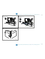
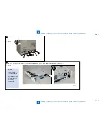
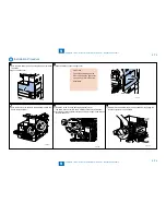
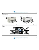
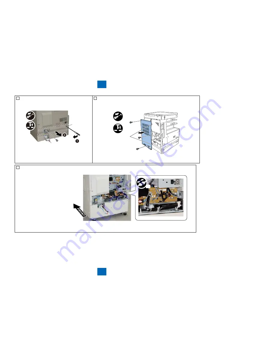
3) Remove the Lower rear cover.
1 Screw
1 Claw
Claw
•
•
F-9-150
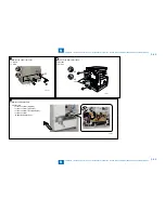
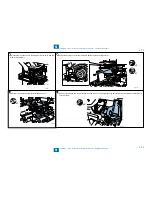
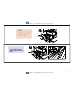
4) Remove the Rear cover (right).
3 Screws
2 Claws
Claws
x3
x2
•
•
F-9-151
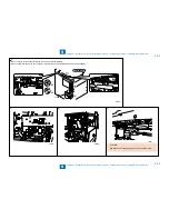
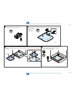
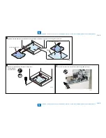
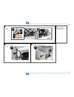
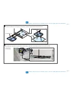
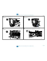
5) Remove
the Heater PCB .
4 Connectors
J1101 connector (SW side).
J1102 connector (PSV side).
J1103 connector (E controller side).
J1106 connector
(Cassette heater side).
•
•
•
•
•
x4
F-9-152
Summary of Contents for IMAGERUNNER 2530
Page 1: ...9 8 7 6 5 4 3 2 1 imageRUNNER 2530 2525 2520 Series Service Manual...
Page 4: ...Blank Page...
Page 16: ...1 1 Product Overview Product Overview Product Lineup Feature Specifications Name of Parts...
Page 111: ...3 3 Periodical Service Periodical Service Consumable Parts and Cleaning Parts...
Page 159: ...5 5 Adjustment Adjustment Outline Adjustment when replacing parts Image position adjustment...
Page 166: ...6 6 Troubleshooting Troubleshooting Upgrading Targets and Procedure...
Page 171: ...7 7 Error Code Error Code Overview Error Code Jam Code Alarm Code...
Page 186: ...8 8 Service Mode Service Mode Outline Details of Service Mode...
Page 321: ...Service Tools General Circuit Diagram Appendix...

