2
2
2-36
2-36
Technology > Image Formation System > Basic Sequence > Sequence of Operation (last rotation)
Technology > Image Formation System > Basic Sequence > Sequence of Operation (last rotation)
Basic Sequence
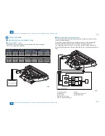
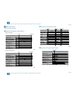
The basic sequence is as follows.
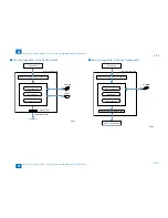
Sequence of Operation (initial rotation)
Pickup from cassette
Pickup
ON
Registration
ON
Primary charging AC bias
Main Motor (M1)
Primary charging DC bias
Laser
Developing AC bias
Developing DC bias
Developing cylinder clutch (CL3)
Transfer bias
Static eliminator bias
Pickup from manual feeder
Multi
ON
Registration
ON
Primary charging AC bias
Main Motor (M1)
Primary charging DC bias
Laser
Developing AC bias
Developing DC bias
Developing cylinder clutch (CL3)
Transfer bias
Static eliminator bias
■
•
•
F-2-55
F-2-55
F-2-56
F-2-56
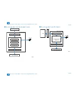
Sequence of Operation (printing)
Primary charging
AC bias
Main Motor (M1)
Primary charging
DC bias
Laser
Developing AC bias
Developing DC bias
Developing cylinder
clutch (CL3)
Transfer bias
Static eliminator bias
Image formation sequence
(1st sheet)
Image formation sequence
(2nd sheet and later)
Sheet-to-sheet
sequence
Registration
ON
Registration
ON
Image write
end
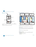
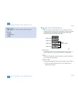
Sequence of Operation (last rotation)
Image write
end
Primary charging AC bias
Main Motor (M1)
Primary charging DC bias
Laser
Developing AC bias
Developing DC bias
Developing cylinder clutch (CL3)
Transfer bias
Static eliminator bias
[1]
In [1] above, a cleaning bias (-2700V) is applied.
■
■
F-2-57
F-2-57
F-2-58
F-2-58
Summary of Contents for IMAGERUNNER 2530
Page 1: ...9 8 7 6 5 4 3 2 1 imageRUNNER 2530 2525 2520 Series Service Manual...
Page 4: ...Blank Page...
Page 16: ...1 1 Product Overview Product Overview Product Lineup Feature Specifications Name of Parts...
Page 111: ...3 3 Periodical Service Periodical Service Consumable Parts and Cleaning Parts...
Page 159: ...5 5 Adjustment Adjustment Outline Adjustment when replacing parts Image position adjustment...
Page 166: ...6 6 Troubleshooting Troubleshooting Upgrading Targets and Procedure...
Page 171: ...7 7 Error Code Error Code Overview Error Code Jam Code Alarm Code...
Page 186: ...8 8 Service Mode Service Mode Outline Details of Service Mode...
Page 321: ...Service Tools General Circuit Diagram Appendix...

