background image

7

6

5

4

3

2

1

imageRUNNER 2530/2525/2520 Series

Service Manual Digest

Periodical Service
Adjustment
Error Code
Service Mode
Parts Replacement and Cleaning
Product Overview
Version Upgrading

Summary of Contents for IMAGERUNNER 2530

Page 1: ...7 6 5 4 3 2 1 imageRUNNER 2530 2525 2520 Series Service Manual Digest Periodical Service Adjustment Error Code Service Mode Parts Replacement and Cleaning Product Overview Version Upgrading ...

Page 2: ...Action to Take after Replacing theMain Controller PCB 2 4 Action to Take when Replacing the DC Controller PCB 2 4 Action to Take after Replacing the RAM 2 5 Laser Exposure System 2 5 Action to Take after Replacing the Laser Scanner Unit 2 5 Image position adjustment 2 5 Margin Along the Leading Edge 2 5 Left Image Margin 2 6 Leading Edge Non Image Width 2 6 Left Non Image Width 2 6 3 Error Code Ov...

Page 3: ...etails 4 35 Method of confirming license option 4 36 Inactivity of the transmitted license 4 36 Erasing a License 4 37 E RDS 4 38 Configuration 4 38 REPORT 4 39 Configuration 4 39 Details 4 39 DOWNLOAD 4 43 Download 4 43 CLEAR 4 44 Configuration 4 44 DISPLAY 4 44 Configuration 4 44 ROM 4 45 Configuration 4 45 TEST MODE 4 45 Outline 4 45 Configuration 4 45 Details 4 46 5 Parts Replacement and Clean...

Page 4: ... delivery image reading options 6 6 Function expanding option 6 7 Basic Configuration 6 8 Functional Configuration 6 8 Basic sequence 6 8 7 Version Upgrading Upgrading Targets and Procedure 7 2 Outline 7 2 Procedure 7 3 ...

Page 5: ...g of Laser System Turn power switch ON Points to Note About Turning Off the Main Power Switch Safety of Toner Notes When Handling a Lithium Battery Notes Before it Works Serving Safety Precautions imageRUNNER 2530 2525 2520 Series ...

Page 6: ...O JAPAN THIS PRODUCT CONHORMS WITH DHHS RADIATION PERFORMANCE STANDARD 21CFR CHAPTER 1 SUBCHAPTER J A different description may be used for a different product Laser Safety When servicing the area around the laser assembly be sure to turn off the main power The machine s covers that can reflect laser light are identified by means of a warning label Figure If you must detach a cover showing the lab...

Page 7: ...F 0 3 Power Supply 1 As a general rule do not use extension cords Using an extension cord may result in a fire or electrical shock If an extension cord must be used however use one for local rated voltage and over untie the cord binding and insert the power plug completely into the extension cord outlet to ensure a firm connection between the power cord and the extension cord 2 The socket outlet s...

Page 8: ...e fibers of the cloth Tonner is easy to react with plastic material avoid contact with plastic Notes When Handling the Lithium and Ni MH Batteries RISK OF EXPLOSION IF BATTERY IS REPLACED BY AN INCORRECT TYPE DISPOSE OF USED BATTERIES ACCORDING TO THE INSTRUCTIONS The following warnings are given to comply with Safety Principles EN60950 Wenn mit dem falschen Typ ausgewechselt besteht Explosionsgef...

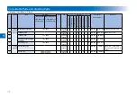
Page 9: ...1 1 Periodical Service Consumable Parts and Cleaning Parts ...

Page 10: ... system Waste toner container FM3 9276 1 80 000 sheets DRBL 1 WST TNR Defined by 6 document 2 Transfer guide 1 120 000 sheets Δ DRBL 1 DVG CYL Wipe with dry cloth 3 Transfer roller FC9 0693 1 150 000 sheets DRBL 1 TR ROLL 4 Separation static charge eliminator FM3 9296 1 150 000 sheets DRBL 1 SP SC EL 5 Developing unit FM3 9263 1 500 000 sheets DRBL 1 DVG CYL 6 Fixing system Fixing inlet guide 1 12...

Page 11: ... FC7 9502 For CHN 1 120 000 sheets DRBL 1 Replace with cassette separation pad Quantity indicates number of cassette 10 Cassette separation roller For 550 sheet cassette FC6 6661 1 120 000 sheets DRBL 1 C1 SP RL C2 SP RL C3 SP RL C4 SP RL Quantity indicates number of cassette 11 Cassette idler gear Only for 550 sheet cassette for China FU3 0280 1 120 000 sheets DRBL 1 Quantity indicates number of ...

Page 12: ... roller 7 Manual feed separation pad 8 Fixing unit 9 Cassette pickup roller 250 sheet 1st cassette model 10 Cassette separation pad 250 sheet 1st cassette model 11 Cassette pickup roller 550 sheet 1st cassette model 12 Cassette transfer roller 550 sheet 1st cassette model 13 Cassette separation roller 550 sheet 1st cassette model 14 Idler gear for China F 1 1 F 1 1 ...

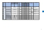
Page 13: ...1 5 1 Cleaning Parts Fixing guide Transfer guide F 1 2 F 1 2 ...

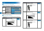
Page 14: ...2 2 Adjustment Overview Adjustment when replacing parts image position adjustment ...

Page 15: ...2 5 Image position adjustment This section describes procedures when adjusting basic image position image margins nonimage area etc Category Item Reference Margin Along the Leading Edge Single sided copy 2 5 1 5 mm Double sided copy 2 5 2 0 mm 2 5 4 6 8 10 12 14 16 18 20 0 2 5 1 5mm 2nd side of double sided copy 2 5 2 0mm Margin Along the Leading Edge page 2 5 T 2 1 T 2 1 Category Item Reference L...

Page 16: ...DER FUNCTION CCD DF WLVL4 Read the white level in the DF mode stream reading Check the transparency of the glass for stream reading Read both sides of the chart Action to Take after Replacing the Platen Glass CAUTION Be sure to make the white plate data adjustment before ADF white level adjustment W PLT X W PLT Y W PLT Z F 2 1 F 2 1 1 Enter the value indicated on the platen glass in the following ...

Page 17: ...g Check the transparency of the glass for stream reading Read both sides of the chart Controller System Action to Take after Replacing theMain Controller PCB After replacing the main controller PCB with a new one take the following action Download the latest firmware with the UST Enter all values recorded on the service label affixed to the rear cover Action to Take when Replacing the DC Controlle...

Page 18: ...horizontal scanning direction magnification ratio adjustment A C PRINT Bitswitch 147 Laser horizontal scanning direction magnification ratio adjustment A D PRINT Bitswitch 148 Laser horizontal scanning direction write position adjustment A B PRINT Bitswitch 149 Laser horizontal scanning direction write position adjustment A C PRINT Bitswitch 150 Laser horizontal scanning direction write position a...

Page 19: ... X 2 5 4 6 8 1012141618 20 0 1st side of copy 2 5 1 5mm Image leading edge Decrease the value a decrease of 10 will decrease the non image width by 1 mm Increase the value an increase of 10 will increase the non image width by 1 mm F 2 4 F 2 4 F 2 5 F 2 5 Left Non Image Width Service mode SCAN READER ADJUST ADJ XY ADJ Y 10 8 6 5 4 2 0 1st side of copy 2 5 1 5mm Image edge Increase the value an inc...

Page 20: ...3 3 Error Code Overview Error Code Jam Code Alarm Code ...

Page 21: ...r PCB PCB4 E001 0000 Title Fixing unit temperature rise detection Description The reading of the main thermistor is 250 deg C or more continuously for 200 msec Remedy 1 Go through the following to clear the error CLEAR ENGIN ERRCLR and then turn OFF and then ON the power 2 Check connection of the Connectors Thermistor Connector and AC Connector 3 Replace the Fixing Main Thermistor Film Unit 4 Repl...

Page 22: ...CB PCB4 Ecode Detail Code Item Description E014 0001 Title Unstable rotation of the Fixing Motor M2 Description Detection is executed every 100 msec after the start of motor rotation however the drive detection signal is absent for 2 sec Remedy 1 Replace the Fixing Motor M2 2 Replace the DC Controller PCB PCB4 E014 0002 Title Unstable rotation of the Fixing Motor M2 Description During motor rotati...

Page 23: ... Title Failure of the Scanner Motor M21 Description The speed lock signal indicates a deviation 10 times in sequence at intervals of 100 msec after the signal has indicated a locked state The same condition is detected after the error retry is performed Remedy 1 Check the cable 2 Replace the Laser Scanner Unit 3 Replace the DC Controller PCB PCB4 E110 0003 Title Failure of the Scanner Motor M21 De...

Page 24: ...5 0001 Title EEPROM error Description The checksum for the EEPROM data has an error Remedy 1 Replace the Finisher Controller PCB PCB1 E520 0001 Title Shift Motor M4 error Description The shift roller does not leave the shift roller home position when the Shift Motor M4 has been driven for 1 2 seconds Remedy 1 Replace the Shift Roller HP Sensor S2 2 Replace the Shift Motor M4 3 Replace the Finisher...

Page 25: ...Shift Roller Release Motor M5 has been driven for 0 06 sec Remedy 1 Replace the Shift Roller Release Sensor S3 2 Replace the Shift Roller Release Motor M5 3 Replace the Finisher Controller PCB PCB1 Ecode Detail Code Item Description E571 0001 Title Gripper Open Close Motor M7 error Description The gripper unit does not leave the gripper unit home position when the Gripper Open Close Motor M7 has b...

Page 26: ...d The same condition is detected after the error retry is performed Remedy 1 Disconnect and then connect the connector J205 on the DC Controller PCB PCB4 2 Replace the Power Supply Cooloing Fan FAN6 3 Replace the DC Controller PCB PCB4 E804 0001 Title Unstable rotation of the Power Supply Cooloing Fan FAN6 Description When lock signal failed to be detected for 5 sec while the Power Supply Cooloing...

Page 27: ...nual or service manual An error code may be either of the following two types User Error Codes A fault indicated as a user error code is one that can easily be corrected by the user as by operating the machine It takes the form of number Service Error Codes If a fault calls for a service man for correction it is indicated as a service man error code in the form of number or SYSTEM ERROR E number M...

Page 28: ... 2 after detection of CM signal from caller causing T1 time out and releasing line 0672 Tx At time of V 34 transmission a shift in procedure from phase 2 to phase 3 and the reafter stops causing the machine to release the line and suffer T1 timeout 0673 Rx At time of V 34 reception a shift in procedure from phase 2 to phase 3 and thereafter stops causing the machine to release the line and suffer ...

Page 29: ...dural signal to be transmitted more than specified 0782 Tx At time of ECM transmission DCN is received after transmission of EOR EOM 0783 Tx At time of ECM transmission the procedural signal has been transmitted more than specified after transmission of EOR EOM or T5 time out 60 sec has occurred 0784 Tx At time of ECM transmission no meaningful signal is received after transmission of EOR EOP caus...

Page 30: ...on sensor S5 3 0207 Stationary jam Fixing outlet sensor S19 3 0208 Stationary jam No 1 delivery sensor S12 3 0209 Stationary jam No 2 delivery sensor S42 3 020A Stationary jam Reversal sensor S40 3 020D Stationary jam Duplex feed sensor S7 3 0A01 Power on jam Cassette 1 pickup sensor S1 3 0A02 Power on jam Cassette 2 pickup sensor SR2 3 0A03 Power on jam Cassette 3 pickup sensor SR4 3 0A04 Power o...

Page 31: ...3 3 12 ACC ID Jam Code Type Sensor Name Sensor ID 3 FF0D Unknown jam 3 FF91 Unknown jam 3 FFF1 Unknown jam T 3 5 T 3 5 DADF AB1 PI10 PI11 PI7 PI6 PI8 PI7 PI6 PI11 PI8 F 3 3 F 3 3 ...

Page 32: ...nt Read sensor PI7 4 0047 Delay jam first document Delivery reversal sensor PI6 4 0048 Stationary jam first document Delivery reversal sensor PI6 4 0071 Timing error 4 0090 ADF open jam Copyboard cover open closed Sensor 0 S21 4 0091 User ADF open jam Copyboard cover open closed Sensor 0 S21 4 0092 ADF cover open jam Cover open closed sensor PI10 4 0093 User cover open jam Cover open closed sensor...

Page 33: ...m Code Details Alarm Code Title A Movement B Cause C Measures 85 0001 E355 clear A Movement Clear process is performed due to E355 error B Cause Mismatch between the serial numbers of Soft ID Flash ROM and FRAM C Measures None 85 0002 Auto restore caused by SoftID Service replacement A Movement Automatic data restore is performed after Soft ID PCB replacement is detected B Cause Soft ID PCP is rep...

Page 34: ...4 4 Service Mode Overview Details of Service Mode ...

Page 35: ...e exchange FAX Do not use SCAN These setting items are for image adjustment in scanning PRINT These setting items are for image adjustment in printer assembly and for special mode for the field related measures NETWORK Use it to confirm the contents of the installed CA certificates CODEC This is a setting items related to CODEC SYSTEM This is a setting items related to SYSTEM ACC Register the acce...

Page 36: ...e OK 6 Press the Stop Additional functions Reset key to end the service mode 033 4 Selecting a Bit Switch Select the bit using the left arrow right arrow on the touch panel SSSW SSSW 000000000 000000000 Operation at the time of Bit SW Operation at the time of Parameter 033 SSSW 000000000 033 SSSW 000000001 2 8 1 Selecting Service Mode 2 8 F 4 1 F 4 1 Setting of Bit Switch Outline Bit Switch Compos...

Page 37: ...ed SW28 00000000 V 8 V 34 protocol settings SW29 not used SW30 00000000 Assigning a New Dial Tone Detection Method SW31 not used SW32 00000000 not used SW33 00000000 counter function settings SW34 00000011 waste toner full display setting SW35 00001000 e RDS function settings SW36 SW50 not used T 4 1 T 4 1 Details SSSW SW01 List of Functions Bit Function 1 0 0 service error code output not output ...

Page 38: ...rom overseas T 4 4 T 4 4 MEMO Any of the following error code may be indicated because of an echo at time of reception 0005 0101 0106 0107 0114 0200 0201 0790 SSSW SW04 List of Functions Bit Function 1 0 0 not used 1 Check CI frequency Yes No 2 the number of final flag sequences of protocol signals 2 1 3 Reception mode after CFR signal transmission high speed high speed low speed 4 the length of t...

Page 39: ...Conversion from mm to inch text photo mode execute do not execute 3 transmit bit 33 and thereafter for DIS signal prohibit do not prohibit 4 Recording paper length availability declared in DIS signal A4 B4 size Arbitrary size 5 not used 6 not used Bit Function 1 0 7 not used Detailed Discussions of Bit 1 Use it to enable disable millimeter inch conversion in sub scanning direction for images read ...

Page 40: ...ngle original page takes 32 min or more To use the timer for a purpose other than this function refer to the tables that follow and select an appropriate time length When do not enable is selected using bit 7 the time out length for a single page for all modes will depend on the setting of bit 0 and bit 1 T 4 7 T 4 7 T 4 8 T 4 8 Time Out Length for Transmission reception Bit7 Bit6 Bit5 Bit4 Bit3 B...

Page 41: ...e line after CI detection 2 Reception of call through caller ID display line main unit line Yes No 3 not used 4 not used 5 not used 6 Detection of continuous signal at fax tel switchover Yes No 7 not used Detailed Discussions of Bit 1 When a dial in fax tel switch cover takes place the polarity of the telephone line is stored in memory for detection of reversal of the polarity of the telephone lin...

Page 42: ... during which the absence of the carrier is detected between DCS and TCF may be set This bit is valid when 1 is set to bit 0 of 1 SSSW SW18 T 4 16 T 4 16 T 4 17 T 4 17 SSSW SW22 List of Functions Bit Function 1 0 0 not used 1 not used 2 not used 3 Prohibit manual polling Yes No 4 not used 5 not used 6 not used 7 not used Detailed Discussions of Bit 3 Selects whether to prohibit by manual polling o...

Page 43: ...xecuted during manual transmission regardless of this setting Detailed Discussions of Bit 3 Select whether to declare the V 8 protocol in DIS signal for reception If NO is selected the V 8 protocol cannot be used because it is not declared in DIS signal The V 8 late start is not executed during manual reception regardless of this setting T 4 20 T 4 20 Detailed Discussions of Bit 4 Select whether t...

Page 44: ...ype1 0 0 New type type2 0 1 New type type3 1 0 New type type4 1 1 Detailed Discussions of Bit 5 Select whether to display the toner cartridge replacement counter T 4 22 T 4 22 T 4 23 T 4 23 T 4 24 T 4 24 When 1 is selected the counter is displayed When 0 is selected the counter is not displayed SSSW SW34 List of Functions Bit Function 1 0 0 Display the waste toner full warning Yes No 1 Switch the ...

Page 45: ...ings 005 NL equalizer 1 ON 0 OFF 006 Telephone line monitor 0 DIAL 1 SERVICEMAN 1 2 SERVICEMAN 2 3 OFF 007 Transmission level ATT From 0 to 15 ex 15 15 dBm 008 V 34 modulation speed upper limit 0 3429 1 3200 2 3000 3 2800 4 2743 5 2400 009 V34 data speed upper limit 0 33 6kbs 1 31 2kbs 2 28 8kbs 3 26 4kbs 4 24 0kbs 5 21 6kbs 6 19 2kbs 7 16 8kbs 8 14 4kbs 9 12 0kbs 10 9 6kbs 11 7 2kbs 12 4 8kbs 13 ...

Page 46: ...re ID code 1 to 60 sec 006 NCC pause time length post ID code 1 to 60 sec 010 line condition identification time length 0 to 9999 10 msec 011 T 30T1 timer for reception 0 to 9999 10 msec 013 T 30 EOL timer 500 to 3000 10 msec 015 hooking detection time length 0 to 999 016 time length to first response at time of fax tel switchover 0 to 9 017 pseudo RBT signal pattern ON time length 0 to 999 018 ps...

Page 47: ...ntification length Use it to set the time for identifying the line connection Raise this parameter if errors occur frequently at time of communication because of the condition of the line MEMO Any of the following error codes may be indicated because of the condition of the line 0005 0018 The line condition identification time is between when the dial signal is transmitted and when the line condit...

Page 48: ...6 of the control panel to suit the needs of the user The default type settings of soft counter is different from models Soft Counter Specifications The soft counters are classified a follows in terms of input numbers 100s total 200s copy 300s print 400s copy print 500s scan 700s received file print 800s report pint 900s transmitted scan Guide to the Table 1 Count sheets of all sizes by one 2 Count...

Page 49: ... 1 1 222 Copy Bk2 2 1 227 Copy Bk L 1 228 Copy Bk S 1 237 Copy Bk L 2 sided 1 238 Copy Bk S 2 sided 1 249 CopyA Bk1 1 1 Serial No on counter check screen Counter type Print system Bk 1 sided L Bk 1 sided S Bk 2 sided L Bk 2 sided S Local copy PDL print FAX print Report print Local copy PDL print FAX print Report print Local copy PDL print FAX print Report print Local copy PDL print FAX print Repor...

Page 50: ...02 Report print Total2 803 Report print L 804 Report print S 809 Report print Bk1 810 Report print Bk2 815 Report print Bk L 816 Report print Bk S 825 Report print Bk L 1 826 Report print Bk S 1 T 4 29 T 4 29 Serial No on counter check screen Counter type Scan system Bk 1 sided L Bk 1 sided S Bk 2 sided L Bk 2 sided S Total scan E mail scan FileShare DBscan E mail FileShare DB scan FileShare DB Bo...

Page 51: ...DISPLAY CCD TARGET B Target value of shading for blue TARGET G Target value of shading for green TARGET R Target value of shading for red OFST Adjustment value of offset level on CIS OFST B not used OFST G not used OFST R not used OFST O not used OFST E not used GAIN Adjustment value of gain level on CIS GAIN B not used GAIN G not used GAIN R not used GAIN O not used GAIN E not used IO R CON Firmw...

Page 52: ...not used MTF3 S2 not used MTF3 S3 not used MTF3 S4 not used MTF3 S5 not used MTF3 S6 not used MTF3 S7 not used MTF3 S8 not used MTF3 S9 not used MTF3 S10 not used Item1 Item2 Item3 Item4 Initial setting Appropriate guideline Description READER ADJUST CCD MTF3 S11 not used MTF3 S12 not used MTF4 M1 not used MTF4 M2 not used MTF4 M3 not used MTF4 M4 not used MTF4 M5 not used MTF4 M6 not used MTF4 M7...

Page 53: ...eter Settings Numeric Prama 033Vertical scan magnification correction Correct the magnification of vertical scanning of a book The larger the adjustment value the more the image stretches in the vertical scanning direction 034 Horizontal scan magnification correction Correct the magnification of horizontal scanning of a book The larger the adjustment value the more the image stretches in the horiz...

Page 54: ...hading for red If the machine continues to display 0 minimum or FFFF maximum there may be some problem on main controller PCB Appropriate guideline 1 to 2047 SCAN READER DISPLAY CCD OFST Adjustment value of offset level on CCD CIS To judge if this adjustment value is correct when an image fault attributed to CCD occurs Appropriate guideline 0 to 255 SCAN READER DISPLAY CCD GAIN Adjustment value of...

Page 55: ...el SCAN READER ADJUST ADJ XY ADJ S Adjustment of CCD CIS scan start cell position image scan start position in horizontal scanning direction T 4 34 T 4 34 Adjust the position to measure data for shading correction with standard white plate This item must not be normally used Note Be sure to enter the value on service label when replacing the CIS unit If changing the setting value of this item be s...

Page 56: ...s item must not be normally used In case of image fault due to chart soil etc after executing SCAN READER FUNCTION CCD DFWLVL1 DF WLVL2 enter the factory measurement value using this mode SCAN READER ADJUST PASCAL OFST P K Density adjustment at test print scanning Execute offset adjustment for test print scanning signal in PASCAL control at auto gradation correction full correction SCAN READER FUN...

Page 57: ...tion screen may appear frequently Reduce the value if users complain because the cleaning instruction screen which appears when dirt is detected is displayed frequently Conversely if the value is reduced too much black streaks may appear on the images When 0 is set the correction control function used when dirt is detected is canceled SCAN FEEDER ADJUST DOCST Adjusting the original stop position f...

Page 58: ... unit 0 1 mm Left end registration adjustment cassette 2 37 100 128 to 127 one unit 0 1 mm Left end registration adjustment cassette 3 38 100 128 to 127 one unit 0 1 mm Left end registration adjustment cassette 4 39 52 Not used 53 25 0 to 9999 one unit 0 1 mm Adjustment of margin at leading edge of copy 54 25 0 to 9999 one unit 0 1 mm Adjustment of margin at trailing edge of copy 55 25 0 to 9999 o...

Page 59: ...78 1 0 to 1 Not used 179 7 0 to 14 Temperature adjustment UP DOWN mode Envelop Postcard 180 7 0 to 14 Temperature adjustment UP DOWN mode Special mode N T 4 35 T 4 35 Item1 Item2 Item3 Default Setting range Function PRINT CST CAS1 CAS1 U1 0 26 OFI 27 E OFI 37 M OFI 36 A OFI 24 FLSP 25 A FLSP 30 A LTRR 42 FA4 34 G LGL 0 default Cassette 1paper size group special standard size paper entry CAS1 U2 0 ...

Page 60: ...on of this mode would degrade the throughput T 4 37 T 4 37 SSSW SW18 List of Functions Bit Function 1 0 0 not used 1 not used 2 Thin postcard mode Enable Disable 3 not used 4 not used 5 not used 6 not used 7 not used Detailed Discussions of Bit 2 When the postcard size is selected Thin postcard can be selected in addition to Postcard Return postcard and 4 on 1card Selecting Enable allows you to sp...

Page 61: ...sary to prevent the paper from slipping or being curled Plain paper Plain paper mode thin paper mode S thin paper mode OHP mode 0 2 15 C 3 11 12 to 15 C in steps of 3 C 12 14 15 C 063 Temperature adjustment UP DOWN mode For rough paper The temperature adjustment offset relative to the target fixing temperature of thick paper can be changed in steps of 3 C Use this parameter when the fixing perform...

Page 62: ...n of laser B of the laser scanner unit Adjust the magnification of laser B with reference to that of laser A If the input value is inappropriate the image quality is degraded 148 Adjustment of the point to start writing in main scanning direction A B When replacing the laser enter the delay value laser main scanning adjustment 151 Developing bias offset for DC Enter the developing bias offset for ...

Page 63: ...this parameter to reduce the FCOT 0 OFF 1 ON 179 Temperature adjustment UP DOWN mode Envelop Postcard The temperature adjustment offset relative to the target fixing temperature of the envelope postcard can be changed in steps of 3 C Use this parameter when the fixing performance is low or when it is necessary to prevent the paper from slipping or being curled Envelop postcard Postcard mode S post...

Page 64: ... U1 U2 U3 and U4 as special size paper in universal size cassettes Settings 22 K LGL 31 G LTR 29 A LTR 0 default CST CAS1 CAS1 U4 CST CAS2 CAS1 U4 CST CAS3 CAS1 U4 CST CAS4 CAS1 U4 Setting of paper name used for paper size group U4 When setting the following special size paper for U1 U2 U3 and U4 which are specified for the paper name to be used in paper size group it becomes possible to treat the...

Page 65: ...ion level at black text processing Adjust the black color recognition level at black text processing To improve chanses that the text color is judged as black increase the setting value T 4 39 T 4 39 SYSTEM Configuration Item No Default Description SYSTEM SW SW01 SW04 Not used SW05 11001000 Inhibition of export of password in address book SW06 SW09 Not used SW10 00000000 PS data protocol menu disp...

Page 66: ...lace when the following service mode is executed CLEAR ALL TYPE SERVICE DATA TEL USER DATA ACC Configuration The table below gives summary description of the accessories available Item1 Item2 Explanation ACC CARD Card reader installation setting Enter a card number to use 0 to 9999 One hundred cards are registered with the department ID beginning from the input card number in sequence 1 1 000 card...

Page 67: ...4 45 T 4 45 Parts counter list Item Counter Explanation Service life DRBL 1 Unit supplies TR ROLL Transfer roller high voltage ON count 150 000 SP_SC_EL Separation static charge eliminator high voltage ON count 150 000 DV UNT C Developing assembly rotation count 500 000 M PU RL Manual feed tray pickup roller paper pass count 150 000 M SP PD Manual tray separation pad paper pass count 150 000 FX UN...

Page 68: ...END function when non transfer is displayed BRDIM 0 0 1 To display installation state of BarDIMM when non transfer is disabled ERDS 0 0 1 To display installation state of third party expansion function of E RDS when non transfer is disabled PCL 0 0 1 To display installation state of PCL function when non transfer is disabled EAM 0 0 1 To display installation state of EAM function when non transfer...

Page 69: ...s service mode This service mode is used to invalidate a license under the assumption that when a device is exceptionally replaced with another one due to a trouble caused by the device the license is transferred to another device This operation is called invalidating transfer of a license Since it is possible to select the same device as a destination of the transfer this service mode can be also...

Page 70: ... section of the sales company and report a function invalidation certificate key required for license transfer the serial number of the transfer origination device and the serial number of the transfer destination device a new license key that can be registered to the transfer destination device is issued 9 Register the new license key to the transfer destination device and make sure that the func...

Page 71: ... 65535 CNT DATE Setting of the date of sending the counter information to the server Valid after input of license Set the start date of the schedule to send the counter information to the server using a third party expansion function of E RDS Refer to the user mode date setting 12 digits YYYYMMDDHHMM YYYY Year MM Month DD Day HH Hour MM Minute CNT INTV 24 1 168 on a weekly basis Setting of the int...

Page 72: ...put of communication error log information related to e RDS T 4 50 T 4 50 Details System Data List Use it to check the settings associated with the service soft switch and service parameters SSSW SW01 00000000 SW02 10000000 SW03 00000000 SW04 10000000 SW05 00000000 SW06 10000000 SW07 00000000 SW08 00000000 SW09 00000000 SW10 00000000 SW11 00000000 SW12 00000011 SW13 00000000 SW14 00000000 SW15 000...

Page 73: ...START TIME 09 02 10 00 OTHER PARTY 12345678 MAKER CODE 10001000 MACHINE CODE 0100001 00000000 RCV V 8 FRAME E0 81 85 D4 90 7E 00 00 SYMBOL RATE 3429 baud DATA RATE 28 8 TX LVL REDUCTION 0 ERR ABCODE 0 ERR SECTXB 0 ERR SECRXB 0 Rx bit 1 00000100 01110111 01011111 00100011 00000001 10101001 00000001 bit 56 bit 57 00000001 00000001 00000100 00000000 00000000 bit 96 Tx bit 1 00000000 01000010 00011111...

Page 74: ...tted 8 RX procedural signal received TX procedural signal transmitted Counter List Explanation Maintenance supplies counter output For more detailed information about the maintenance supplies counter output refer to COUNTER page 4 34 Error Log List JAM ERR LOG REPORT 07 12 2005 13 07 FAX 001 1 2 3 4 5 6 7 8 9 10 1 2 3 4 5 6 7 8 JAM 01 04 12 12 17 20 03 4 1 0012 000026 1 A4 20 04 12 12 17 20 03 4 1...

Page 75: ...s occurred 2 Alarm date Date of alarm occurrence 3 Alarm time 4 Alarm recovery time 5 Location 6 Alarm code Alarm code 4 digit code for a definition of the code see the Alarm Code page 3 14 7 Detail code Detail code of the alarm code 8 digit code for a definition of the code see the Error Code Chapter T 4 52 T 4 52 T 4 53 T 4 53 T 4 54 T 4 54 Spec List SPEC REPORT 2009 10 09 16 31 0001 TYPE LBP SP...

Page 76: ...FF OFF OFF OFF OFF OFF ON OFF ON OFF ON OFF ON OFF ON OFF ON OFF ON OFF ON OFF ON OFF ON OFF ON OFF ON OFF ON OFF ON OFF FUYxxxxx 20080042 1 AB XXX 000688 000685 000000 000000 000000 000000 000000 000000 000000 000000 000000 0MB OFF 0MB 00XXXXXXXX 00 00 85 51 60 1C 0 0 0 0 0 0 0 3 0 0 0 ON 11 12 8 9 10 14 13 6 7 1 Type setting 2 Print speed 3 Memory size 4 ROM version MAIN BOOT LANG 1 language lib...

Page 77: ...ings Displayed only after activation of the e RDS function DEPT_USER_CLEAR Turns off the department based ID management and user management functions SYSTEM_INFO_CLEAR Clears the system management identification number ENGIN ERRCLR Clears the engine errors BKRAMCLR Clears the engine backup RAM TNRINST Supplies toner from the toner cartridge to the developing assembly EAM DAT Initializes the EAM Fl...

Page 78: ...verify the operations of microswitches sensors speakers and ADF functions T 4 57 T 4 57 Configuration Numerals enclosed in parentheses denote a numeric keypad key to be pressed each Group subgroup Item 1 Item2 Item3 Explanation TEST MODE 1 9 1 DRAM 1 2 D RAM data check 1 D RAM TEST Write read check 2 D RAM TEST Read check 3 PG SELECT NO 01 Grid SELECT NO 02 HT SELECT NO 03 All black output SELECT ...

Page 79: ...s of D RAM SDRAM If an error occurs making this check the test is aborted with an error appearing on the touch panel LCD T 4 58 T 4 58 Numeric keypad key 2 Checks to see if data can be correctly read from all areas of D RAM SDRAM If an error occurs making this check the test is aborted with an error appearing on the touch panel LCD D RAM TEST 29888KB D RAM TEST 29888KB Press numeric keypad key 1 2...

Page 80: ...ck and the speaker 5 DTMF signal reception test Use it to generate the DTMF signal coming from the modem using the telephone line terminal and the speaker 6 Tonal signal reception test Use it to monitor a specific frequency and the DTMF signal received from the telephone line terminal by causing them to be indicated on the LCD i e the presence absence as detected The reception signal is generated ...

Page 81: ... speaker The number pressed on the keypad selects a specific DTMF signal T 4 61 T 4 61 T 4 62 T 4 62 MEMO The output level of individual signals is in keeping with the setting made in service mode Tonal DTMF Signal Reception Test A press on 6 on the keypad from the MODEM test menu selects the tonal signal DTMF signal reception 0 test In this signal the tonal signal DTMF signal received from the te...

Page 82: ...atus of the unit sensors from the touch panel LCD indications Press numeric keypad key 3 on the FUNCTION TEST menu to select the sensor test To select a minor item press the START key The touch panel LCD indications change as the associated sensors turn on and off Group Item Description Detail 2 SENS SW CHECK FLAG Sensor check with flag manual check CT Waste Toner Full Sensor S17 0 Full 1 Availabl...

Page 83: ...r S5 0 Document presence 1 Document absenc RP Loop Sensor S6 0 Document presence 1 Document absenc FX Fixing Outlet Sensor S19 0 Document presence 1 Document absenc D1 2 No 1 Delivery Sensor S12 No 2 Delivery Sensor S42 0 Document presence 1 Document absenc TU Reversal Sensor S40 0 Document presence 1 Document absenc DL Duplex Feed Sensor S7 0 Document presence 1 Document absenc ADF ADF sensor che...

Page 84: ... Test menu 1 Press numeric keypad key 1 on the LINE DETECT menu to select test menu 1 When CI is detected on the telephone line connection terminal the touch panel LCD display changes from OFF to ON indicating the received frequency The touch panel LCD also displays the on hook or off hook state of an external telephone set as detected The touch panel LCD displays from left to right CI CI frequenc...

Page 85: ...5 5 Parts Replacement and Cleaning List of Parts ...

Page 86: ...el FM3 9356 TW FM3 9354 UL AU FM3 9355 CN FM3 9357 KR FM3 9358 EUR 5 Support Cover 6 Delivery Tray FC9 0513 7 Front Cover FM3 9256 8 Cassette 1 9 Cassette 2 Only for the Cassette 2 standard model 10 Lower Left Cover 550 sheet 1st cassette type FC9 0506 250 sheet 1st cassette type FC9 1001 11 Left Cover FM3 9338 12 Inside Base Cover FC9 0520 13 Rear Left Cover FC9 0523 14 Toner Supply Cover FC9 057...

Page 87: ...ar Cover Right FC9 0525 19 Rear Cover Left FC9 0524 20 Right Cover Upper Rear FC9 0572 21 Right Cover Lower Rear 550 sheet 1st cassette type FC9 0527 250 sheet 1st cassette type FC9 1008 000 22 Manual Feed Pickup Tray FM3 9285 23 Right Cover FM3 9284 With No 2 Deleivery Unit FM3 9380 Without No 2 Deleivery Unit 24 Lower Rear Cover 550 sheet 1st cassette type FC9 0507 250 sheet 1st cassette type FC...

Page 88: ...kup Unit FM3 9372 3 Laser Scanner Unit FM3 9406 4 No 2 Deleivery Unit FM3 9314 5 Toner Supply Unit FM3 9428 6 Right Cover Unit FM3 9284 With No 2 Deleivery Unit FM3 9380 Without No 2 Deleivery Unit 7 Platen Glass AB INCH SIZE FL3 3143 A INCH SIZE FL3 3190 A SIZE FL3 3191 AB SIZE FL3 3155 8 ADF Scan Glass FL3 3144 ...

Page 89: ...74 250 sheet 1st cassette type 230V FM3 9361 PCB4 DC Controller PCB 550 sheet 1st cassette type FM4 2864 250 sheet 1st cassette type FM4 2865 PCB5a LCD Unit FL3 3204 PCB5b 1 4 Inverter PCB FM2 2753 PCB5c Control Panel CPU PCB FM4 2854 PCB5d Key Top PCB Assembly FM4 2855 PCB6 HVT PCB FM4 2872 PCB7 Option Power Supply PCB 120V FK2 9187 230V FK2 9188 PCB10 Heater PCB 120V FM4 2857 230V FM4 2858 PCB11...

Page 90: ...5 5 6 List of Solenoids SL3 SL1 SL2 SL5 SL4 F 5 5 F 5 5 Symbol Part name Part number SL1 Pickup Solenoid FK2 0408 SL2 Manual Feed Pickup Solenoid FK2 1410 SL3 No 1 Delivery Reversal Solenoid FK2 9195 ...

Page 91: ...5 7 5 List of Sensors S18 S17 S16 TS2 HU1 S9 S8 S19 TS1 S11 S12 F 5 6 F 5 6 S4 S3 S2 S1 S5 S6 S31 S7 S33 S32 S36 A INCH S37 S34 S41 S42 S40 S35 S36 AB INCH F 5 7 F 5 7 ...

Page 92: ... WG8 5836 S12 No 1 Delivery Sensor WG8 5836 S16 Toner Cover Open Closed Sensor WG8 5836 S17 Waste Toner Full Sensor WG8 5836 S18 Front Cover Open Closed Sensor WG8 5836 S19 Fixing Outlet Sensor WG8 5836 S31 Cis Hp Sensor WG8 5696 S32 Copyboard Cover Open Closed Sensor 0 WG8 5696 S33 Copyboard Cover Open Closed Sensor 1 WG8 5696 S34 Original Size Sensor 0 FH7 7569 S35 Original Size Sensor 1 FH7 756...

Page 93: ... M6 M10 F 5 8 F 5 8 Symbol Part name Part number M1 Main Motor FK2 9141 M2 Fixing Motor FK2 9145 M3 Cassette 1 Pickup Motor FK2 7327 M6 Bottle Motor FK2 9147 M7 Hopper Motor FK2 9147 M10 Reversal Motor FK2 9150 M31 Scanner Motor FK2 1066 ...

Page 94: ...5 5 10 List of Fans FAN6 FAN3 FAN4 F 5 9 F 5 9 Symbol Part name Part number FAN3 Exhaust Fan Rear FK2 0360 FAN4 Exhaust Fan Front FK2 0360 FAN6 Power Supply Cooling Fan FK2 0360 ...

Page 95: ...itches SW2 SW6 SW7 SW4 F 5 10 F 5 10 Symbol Part name Part number SW2 Front Door Switch WC4 5242 SW4 Enviorment Switch FM4 2876 SW6 Cassette Size Detection Switch 1 WC2 5680 SW7 Cassette Size Detection Switch 2 WC2 5680 ...

Page 96: ...art number iR2530 2525 550 sheet 1st cassette type iR2530 2525 2520 250 sheet 1st cassette type CL1 Registration Clutch FK2 9154 CL2 Manual Feed Pickup Clutch Cassette Manual Feed Pickup Clutch FK2 9154 CL3 Developing Cylinder Clutch FK2 9154 CL4 Duplex Feed Clutch FK2 9154 ...

Page 97: ...Part number TH1 Fixing Main Thermistor 120V FM4 3367 230V FM3 9381 TH2 Fixing Sub Thermistor H1 Fixing Heater 1 H2 Fixing Heater 2 SP1 Speaker Option FK2 9442 H3 Cassette Heater Option FM3 8915 H4 Drum Heater Option FK2 9157 H5 Reader Heater Option 120V FK2 9468 230V FK2 0228 ...

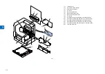
Page 98: ...6 6 Product Overview Specifications Product lineups Basic Configuration ...

Page 99: ...h ISO C5 DL The optional Envelope Feeder Attachment D1 is required Item Specifications Paper type Manual feed pickup tray Weight 64 g m2 to 128 g m2 Type Plain Recycled Color 64 g m2 to 80 g m2 3 hole punch Bond 75 g m2 to 90 g m2 Heavy Paper 1 81 g m2 to 90 g m2 Heavy Paper 2 91 g m2 to 105 g m2 Heavy Paper 3 106 g m2 to 128 g m2 Transparencies Labels Envelopes No 10 COM10 ISO B5 Monarch ISO C5 D...

Page 100: ...ssette Approx 50 5 kg T 6 1 T 6 1 Weight Size Product name Width mm Depth mm Height mm Weight Approx kg imageRUNNER 2530i 2530 2525i 2525 with the platen cover 565 680 806 50 5 with the single cassette imageRUNNER 2530i 2530 2525i 2525 with the feeder 565 693 896 77 5 with the double cassette and 2 way unit imageRUNNER 2520i 2520 with the platen cover 565 680 681 50 5 with the single cassette imag...

Page 101: ...he 2 way unit Plain paper 64 90 9 9 9 9 9 9 Heavy Paper 91 105 106 128 T 6 3 T 6 3 Paper type For free size paper refer to the table below Type Feeding direction mm Width direction mm Free size 148 to 432 99 to 297 Pickup Usable paper types are shown Paper type g m2 Size Manual feed pickup tray Cassette 1 Cassette 2 Cassette 3 Cassette 4 with the envelope feeder without the envelope feeder Plain 6...

Page 102: ...dard or optional Printer Model type imageRUNNER 2530 imageRUNNER 2525 imageRUNNER 2520 Print Speed 30ppm 25ppm 20ppm Positioning Target machine imageRUNNER 2025 2022 2018 Series imageRUNNER 2530 2525 2520 Underlined 2 digit numeric figures indicate print speed ppm print per minute T 6 6 T 6 6 T 6 7 T 6 7 F 6 2 F 6 2 ...

Page 103: ... Cover Type P 8 Document Tray J1 9 FL Cassette AJ1 10 FL Cassette AK1 11 FL Cassette AL1 12 Cassette Heater Unit 37 Cst Heater Kit J1 is required 13 Cassette Module W1 Cassette Spacer A1 is required when installing to 250 Sheets Cassette Model 14 CST Feeding Unit AE1 Cassette Spacer A1 is required when installing to 250 Sheets Cassette Model 15 Envelope Feeder Attachment D1 16 Cassette Spacer A1 1...

Page 104: ...Port Interface Kit A1 5 Serial Interface Kit J2 6 System Upgrade RAM C1 7 System Upgrade SD Card A1 8 Copy Control Interface Cable A1 9 Barcode Printing Kit B1 PCL Printer Kit AF1 is required 10 PCL Printer Kit AF1 System Upgrade RAM C1 is required 11 PS Printer Kit AF1 System Upgrade RAM C1 is required 12 Color Send Kit Y1 System Upgrade RAM C1 is required 13 Color Send Searchable PDF Kit C1 Syst...

Page 105: ...em Duplexing feed Delivery Transfer Pickup Fixing Fixing system Image formation system Pickup feed system Laser exposure system Cassette 2 Cassette 1 Laser scanner unit F 6 5 F 6 5 Basic sequence Sequence at Power On Reader Backwarding Main power switch ON SREADY STBY Scanner motor LED CIS HP sensor Shading position Shading position Forwarding Print sequence Reader Book mode 1 original Backwarding...

Page 106: ...7 7 Version Upgrading Upgrading Targets and Procedure ...

Page 107: ...OT_vXXXX There are two types of main controllers Note When upgrading two types of firmware Boot and Bootable lang at the same time upgrade Boot first Program USTUPDATE_iR2545_35_ bootable_lang_WLaaXXXX iR2530 2525 2520 Boot USTUPDATE_iR2530_25_ 20_BOOT_vXXXX Program USTUPDATE_iR2530_25_ 20_bootable_lang_WLaaX XXX DC controller PCB iR2545 iR2535 DCON USTUPDATE_iR2545_35_ DCON_vXXXX There are three ...

Page 108: ...ard appears Click Cancel 3 Enter the service mode key 2 Key 8 Key key 4 Select DOWNLOAD by pressing the arrow key then press the OK key MEMO You can also enter the download mode from the following user mode System Settings Firmware Upgrade Yes 5 When USB DOWNLOAD AVAILABLE is displayed start up the UST F 7 2 F 7 2 6 Click Next following the instruction shown on the screen 7 Click Next following th...

Page 109: ...cify by printer name is not displayed F 7 6 F 7 6 F 7 5 F 7 5 9 Click Start following the instruction shown on the screen 10 Click Yes following the instruction shown on the screen 11 The following screen appears UPDATING FIRMWARE is displayed on the control panel of this machine F 7 7 F 7 7 F 7 8 F 7 8 F 7 9 F 7 9 ...

Page 110: ...ress Do not turn OFF the power while the system software is being downloaded or written The machine may fail to start when the power is turned ON 12 When upgrade is complete the following screen appears Turn OFF then ON the main power switch to complete the procedure F 7 10 F 7 10 ...

Reviews: