CHAPTER 4 IMAGE FORMATION SYSTEM
4-24
COPYRIGHT © 1999 CANON INC. CANON imageRUNNER 400/330 REV.0 JAN. 1999 PRINTED IN JAPAN (IMPRIME AU JAPON)
B. IP PCB
1. Removing the IP PCB
1) Remove the copyboard glass.
2) Remove the CCD unit cover.
3) Remove the screw of the original size
sensor mount (right), and keep it away
from the IP cover. (Figure 4-502)
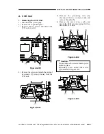
4) Remove the four screws [1], and detach
the IP cover [2] (small window).
Figure 4-404
5) Disconnect the two connectors of the
original sensor mount (right; step 3)).
6) Remove the screw [4], and disconnect the
two connectors [5]; then, detach the
original sensor mount (left) [3].
Figure 4-405
7) Disconnect the 11 connectors of the IP
PCB [6].
Caution:
Do not forget to disconnect the
connector [8].
8) Remove the seven screws [7] of the P
PCB; then, detach the IP PCB.
Figure 4-406
Caution:
When moving the No. 1 mirror mount
unit to the home position, be sure not to
apply force.
When mounting the image processor
PCB, take care no to inadvertently route
the harness connecting the image
processor PCB and the BD PCB over
the light-receiving face of the BD PCB.
Such would hinder correct BD
detection.
[1]
[1]
[1]
[2]
[4]
[3]
[5]
[7]
[6]
[8]
[7]
[8]
[7]
[8]
[8]
[7]
[7]
[7]
[7]
[8]
[8]
[8]


