CHAPTER 7 PICK-UP/FEEDING SYSTEM
7-38
COPYRIGHT © 1999 CANON INC. CANON imageRUNNER 400/330 REV.0 JAN. 1999 PRINTED IN JAPAN (IMPRIME AU JAPON)
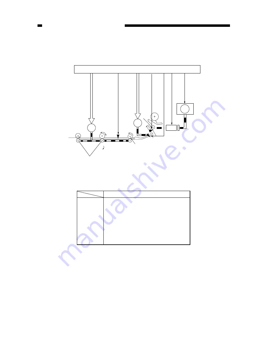
Figure 7-134 and Table 7-108 show the electrical parts associated with the detection of rear/
front registration.
Figure 7-134
Table 7-108
M1
M6
M9
LC3
PS11
PS9
PS10
Electrical parts
Main motor
Lower feeder roller
Horizontal registration sensor shift motor
Vertical path clutch
Vertical path sensor
Re-pick up sensor
Horizontal sensor
PS9
PS11
M1
M9
PS10
CL3
M6
J114
J102-B11
MMD
J114-B5
PS9S
J102-B9
PS10S
J108-B8
PS11S
CL3D*
J108-A4
J102
DC controller PCB
Duplexing feeding roller
Duplexing assembly outlet roller


