CHAPTER 11 SYSTEM INTEGRATION
11-10
COPYRIGHT © 1999 CANON INC. CANON imageRUNNER 400/330 REV.0 JAN. 1999 PRINTED IN JAPAN (IMPRIME AU JAPON)
Caution:
If you are installing the extension unit to
the copier, make sure that the connector
screw holes are positioned as shown
before fitting the screw.
Screw hole in
the extension kit
Screw hole in
the copier
Match the
screw holes.
Extension unit
Figure 11-309
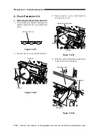
B. SCSI Interface Board
1. Removing the SCSI Interface Board
1) Check to see that the Communication
Memory lamp is off; then, turn off the
main power.
2) Remove the terminator.
Figure 11-310
3) If the printer board is installed, remove the
PCL face cover shown in the figure.
Terminator
Figure 11-311
Screw
Screw
PCL face cover

