CHAPTER 14 TROUBLESHOOTING
14-20
COPYRIGHT © 1999 CANON INC. CANON imageRUNNER 400/330 REV.0 JAN. 1999 PRINTED IN JAPAN (IMPRIME AU JAPON)
E. Fixing System
1
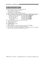
When Mounting the Fixing
Heater
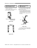
1) Do not touch the heater surface.
2) Orient it so that the side with the longer
heater wire is toward the front.
3) Mount the main heater (700 W) to the
right and the sub heater (600 W) to the left
when viewing the fixing assembly from
the front.
4) Connect the right faston of the heater to
the main heater and the upper faston to the
sub heater when viewing it from the rear.
(The fastons are found at the rear.)
Main heater
Sub heater
(Delivery side)
(pick-up side)
Upper fixing roller
Figure 14-226
2
Positioning the Fixing
Assembly Paper Guide
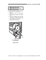
Caution:
If you removed the inlet guide plate, you
would need to adjust the position of the
inlet guide. To avoid the work, do not
loosen the mounting screw (paint-
locked) on the inlet guide mount;
otherwise, be sure to set it to its initial
position by referring to the scale on the
fixing assembly.
3
Adjusting the Lower Fixing
Roller Pressure (nip)
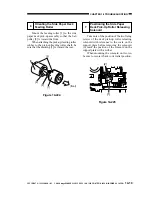
If you have replaced the upper fixing
roller or the lower fixing roller, or if fixing
faults occur, make the following adjustments:
If you are taking measurements while the
fixing roller is cold, leave the machine alone
for 15 min after it ends its wait period and
make 20 copies before taking measurements:
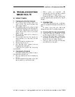
<Taking Measurements>
1) Make an A4 solid black copy, and make a
copy of it. Set the output in the
multifeeder.
2) Select NIP-CHK in service mode
(FUNCTION>FIXING), and press the
OK key.
3) The paper will be picked up and is stopped
between the fixing rollers temporarily;
then, it will automatically be discharged
in about 20 sec.
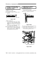
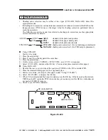
4) Measure the width of the area where toner
is shiny (Figure 14-227).
Figure 14-227
Caution:
a and c are points 10 mm from both
edges of the copy paper.
c
a
Center of
the copy
b
A3
(Feeding
direction)
* Measured when the upper/lower roller is
adequately heated.
Table 14-201
Point
b
a-c
Measurements*
5.5 ±0.3 mm
0.5 mm or less

