Chapter 4
4-14
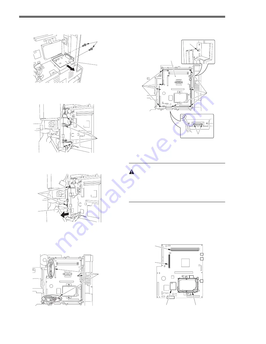
4) Remove the reader I/F PCB [1].
- 2 screws [2]
F-4-23
5) Disconnect the 4 connectors [1] of the video
PCB.
F-4-24
6) Remove the video PCB unit [1].
- 2 screws [2]
F-4-25
4.6.2.2 Removing the Main Controller
PCB
0010-8730
1) Disconnect the 11 connectors [1].
F-4-26
2) Remove the main controller PCB [1].
- 9 screws [2]
- 2 screws [3] (using a precision screwdriver)
F-4-27
4.6.2.3 When Replacing the Main
Controller PCB
0010-8734
Before Starting the Work (backing up the
data)
If possible, perform the following:
- Using the SST, download the data stored in the
RAM of the main controller.
- Print out the user mode/service mode data.
- If you are replacing the main controller PCB, be
sure to physically transfer the following from
the existing to the new PCB:
[1] BootROM
[2] HDD
[3] image memory (DDR-SDRAM)
[4] counter memory PCB
F-4-28
[1]
[2]
[1]
[2]
[1]
[1]
[1]
[2]
[2]
[2]
[3]
[1]
[2]
[3]
[4]
Summary of Contents for IMAGERUNNER 7095 PRINTER
Page 20: ...Chapter 1 Introduction...
Page 46: ...Chapter 2 Installation...
Page 88: ...Chapter 3 Basic Operation...
Page 94: ...Chapter 4 Main Controller...
Page 116: ...Chapter 5 Original Exposure System...
Page 165: ...Laser Exposure Chapter 6...
Page 175: ...Chapter 7 Image Formation...
Page 231: ...Chapter 8 Pickup Feeding System...
Page 287: ...Chapter 9 Fixing System...
Page 312: ...Chapter 10 External and Controls...
Page 346: ...Chapter 11 MEAP...
Page 350: ...Chapter 12 RDS...
Page 360: ...Chapter 13 Maintenance Inspection...
Page 375: ...Chapter 14 Standards Adjustments...
Page 407: ...Chapter 15 Correcting Faulty Images...
Page 433: ...Chapter 16 Self Diagnosis...
Page 460: ...Chapter 17 Service Mode...
Page 559: ...Chapter 18 Upgrading...
Page 583: ...Chapter 19 Service Tools...
Page 588: ...APPENDIX...
Page 615: ......


