Chapter 14
14-15
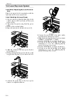
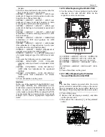
2) Arrange the mirror positioning tool so that it is
ready for use in the machine (by changing the
pin position; FRONT).
F-14-28
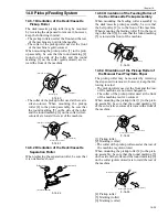
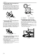
3) Fit the pins of the mirror positioning tool (front
[2]; rear [3]) into the appropriate holes of the
No. 1/No. 2 mirror base).
F-14-29
F-14-30
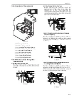
4) Secure the end of the cable that has temporarily
been fixed in place on the hook of the reader
unit frame.
5) Fully tighten the screws on the cable fixing
plate both at the front and the rear.
6) Detach the mirror positioning tool (FRONT,
REAR).
7) Put the detached parts back on by reversing the
foregoing steps.
[A]
[B]
[C]
[B]
[A]
[1]
[3]
[2]
Summary of Contents for IMAGERUNNER 7095 PRINTER
Page 20: ...Chapter 1 Introduction...
Page 46: ...Chapter 2 Installation...
Page 88: ...Chapter 3 Basic Operation...
Page 94: ...Chapter 4 Main Controller...
Page 116: ...Chapter 5 Original Exposure System...
Page 165: ...Laser Exposure Chapter 6...
Page 175: ...Chapter 7 Image Formation...
Page 231: ...Chapter 8 Pickup Feeding System...
Page 287: ...Chapter 9 Fixing System...
Page 312: ...Chapter 10 External and Controls...
Page 346: ...Chapter 11 MEAP...
Page 350: ...Chapter 12 RDS...
Page 360: ...Chapter 13 Maintenance Inspection...
Page 375: ...Chapter 14 Standards Adjustments...
Page 407: ...Chapter 15 Correcting Faulty Images...
Page 433: ...Chapter 16 Self Diagnosis...
Page 460: ...Chapter 17 Service Mode...
Page 559: ...Chapter 18 Upgrading...
Page 583: ...Chapter 19 Service Tools...
Page 588: ...APPENDIX...
Page 615: ......


