Chapter 14
14-28
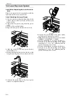
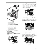
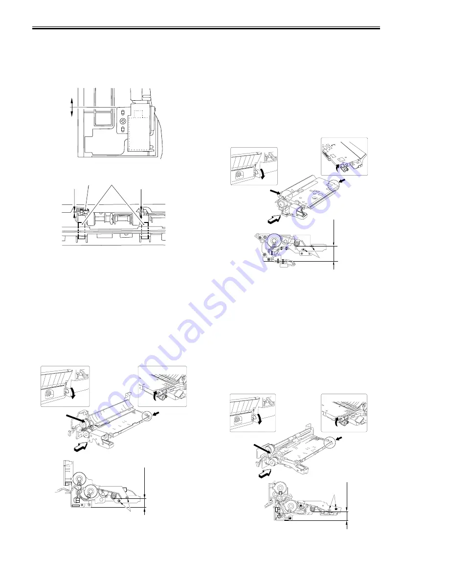
14.8.13 Position of the Multifeeder Latch
Solenoid (SL6)
0010-9352
Slide the solenoid in the direction of A so that the
gap between the shutter [1] and the shutter plate
[2] is 0.4 -/+ 0.2 mm when the solenoid is drawn.
F-14-65
F-14-66
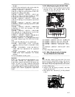
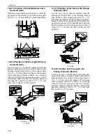
14.8.14 Position of the Deck (right) Pickup
Solenoid (SL7)
0010-9353
Use the screw [3] so that the distance from the
pickup unit bottom of each cassette holder and the
bushing bottom edge of the A roller support plate
is 34.0 -/+ 0.5 mm when the plunger of the pickup
roller releasing solenoid is drawn (as occurring
when [1] and [2] are operated as shown). (After
adjustment, make sure that the distance between
the paper face and the A roller is 2.5 -/+ 0.5 mm
when the A roller is in UP position.)
F-14-67
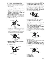
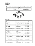
14.8.15 Position of the Deck (Left) Pickup
Solenoid (SL8)
0010-9354
Use the screw [3] so that the distance from the
pickup unit bottom face to the bushing bottom
edge of the A roller support plate is 49.5 -/+ 0.5
mm when the plunger of the pickup releasing so-
lenoid is drawn (as occurring when [1] and [2] are
operated as shown). (After adjustment, make sure
that the distance between the paper face and the A
roller is 2.5 -/+ 0.5 mm when the A roller is in UP
position.)
F-14-68
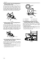
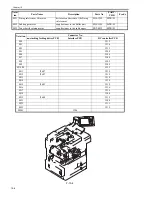
14.8.16 Position of the Cassette 3/4
Pickup Solenoid (SL9/10)
0010-9356
Use the screw [3] so that the distance from the pick-
up unit bottom face of each cassette holder and the
bushing bottom edge of the A roller support plate is
35.5 -/+ 0.5 mm when the plunger of the pickup
roller releasing solenoid is drawn (as occurring
when [1] and [2] are operated as shown). (After ad-
justment, make sure that the distance between the
paper face and the A roller is 2.5 -/+ 0.5 mm when
the A roller is in UP position.)
F-14-69
A
[1]
[2]
0.4±0.2mm
0.4±0.2mm
[1]
[1]
[2]
[2]
A
View from A
34.0±0.5mm
[3]
[2]
[1]
[1]
[2]
A
View from A
49.5±0.5mm
[3]
[1]
[2]
[1]
[2]
A
View from A
35.5±0.5mm
[3]
Summary of Contents for IMAGERUNNER 7095 PRINTER
Page 20: ...Chapter 1 Introduction...
Page 46: ...Chapter 2 Installation...
Page 88: ...Chapter 3 Basic Operation...
Page 94: ...Chapter 4 Main Controller...
Page 116: ...Chapter 5 Original Exposure System...
Page 165: ...Laser Exposure Chapter 6...
Page 175: ...Chapter 7 Image Formation...
Page 231: ...Chapter 8 Pickup Feeding System...
Page 287: ...Chapter 9 Fixing System...
Page 312: ...Chapter 10 External and Controls...
Page 346: ...Chapter 11 MEAP...
Page 350: ...Chapter 12 RDS...
Page 360: ...Chapter 13 Maintenance Inspection...
Page 375: ...Chapter 14 Standards Adjustments...
Page 407: ...Chapter 15 Correcting Faulty Images...
Page 433: ...Chapter 16 Self Diagnosis...
Page 460: ...Chapter 17 Service Mode...
Page 559: ...Chapter 18 Upgrading...
Page 583: ...Chapter 19 Service Tools...
Page 588: ...APPENDIX...
Page 615: ......


