Chapter 2
2-20
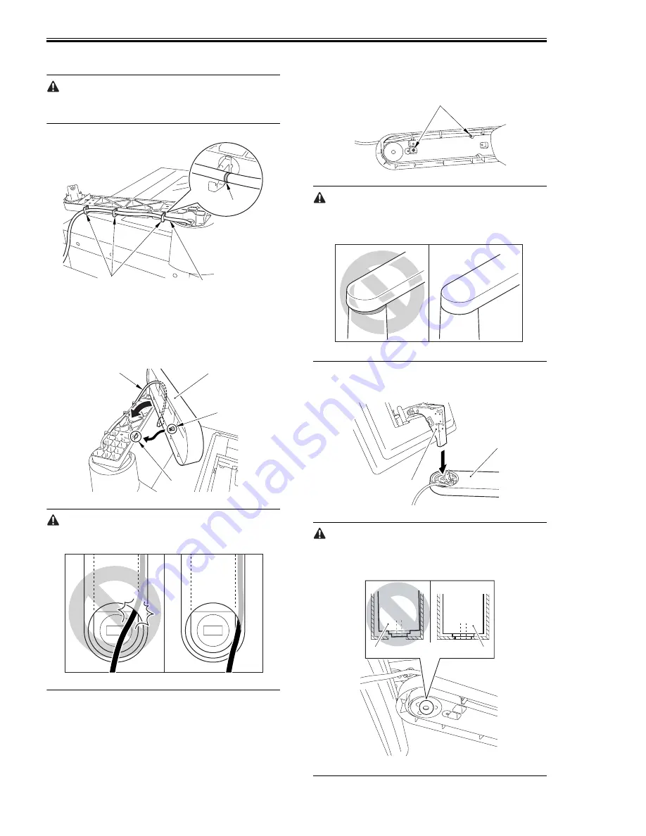
13) Fix the control panel interface cable [1] in
place using the 3 wire saddles [2].
Match the wire saddle at the rear and the marking
[3].
F-2-71
14) Route the control panel interface cable [1]
through the arm cover 1 [2].
15) Hook the claw [3] on the cut-off [4] of the arm
unit, and put the arm cover 1 [2] in place.
F-2-72
Take care not to trap the cable.
F-2-73
16) Fix the arm cover 1 in place from behind the
arm unit.
- 2 screws (P tightening; M4x10) [1]
F-2-74
Make sure there is no discrepancy between the
arm cover 1 and the arm cover 2.
F-2-75
17) Fit the shaft [1] of the control panel in place
on the arm unit [2].
F-2-76
Fit the tip of the shaft [1] of the control panel in
the round hole of the arm unit.
F-2-77
[2]
[1]
[3]
[1]
[4]
[3]
[2]
[1]
[1]
[2]
[1]
[1]
Summary of Contents for IMAGERUNNER 7095 PRINTER
Page 20: ...Chapter 1 Introduction...
Page 46: ...Chapter 2 Installation...
Page 88: ...Chapter 3 Basic Operation...
Page 94: ...Chapter 4 Main Controller...
Page 116: ...Chapter 5 Original Exposure System...
Page 165: ...Laser Exposure Chapter 6...
Page 175: ...Chapter 7 Image Formation...
Page 231: ...Chapter 8 Pickup Feeding System...
Page 287: ...Chapter 9 Fixing System...
Page 312: ...Chapter 10 External and Controls...
Page 346: ...Chapter 11 MEAP...
Page 350: ...Chapter 12 RDS...
Page 360: ...Chapter 13 Maintenance Inspection...
Page 375: ...Chapter 14 Standards Adjustments...
Page 407: ...Chapter 15 Correcting Faulty Images...
Page 433: ...Chapter 16 Self Diagnosis...
Page 460: ...Chapter 17 Service Mode...
Page 559: ...Chapter 18 Upgrading...
Page 583: ...Chapter 19 Service Tools...
Page 588: ...APPENDIX...
Page 615: ......


