

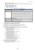
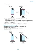
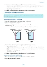


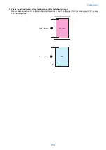

5. If it is not within the standard range, make an adjustment with the following service mode
• FEEDER > ADJUST > LA-SPD2
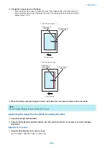
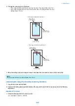
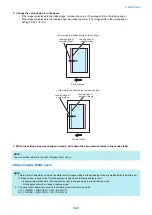
If the image on the Print 2 is longer: Make the numeric value larger (by making the vertical scanning length of the image
shorter).
If the image on the Print 2 is shorter: Make the numeric value smaller (by making the vertical scanning length of the
image longer).
• Amount of change per increment: 0.1%
• Adjustment range: -30 to +30
6. Print the test chart again, and check that the image is within the ranges of the standard.
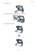
■ White level adjustment
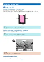
1. Place a sheet of blank A4 or LTR size paper on the Copyboard Glass and close the ADF.
CAUTION:
When executing the white level adjustment using paper with smaller width, adjustment may not be executed properly.
2. Execute the service mode item.
• COPIER > FUNCTION > CCD > DF-WLVL1
3. Remove the blank paper from the Copyboard Glass, and place it on the Document Pickup Tray of ADF.
4. Execute the service mode item.
• COPIER > FUNCTION > CCD >DF-WLVL2
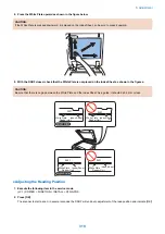
5. Place the blank paper on the Copyboard Glass again and close the ADF.
6. Execute the service mode item.
• COPIER > FUNCTION > CCD > DF-WLVL3
7. Remove the blank paper from the Copy Board Glass, and place it on the Document Pickup Tray of ADF.
8. Execute the service mode item.
• COPIER > FUNCTION > CCD > DF-WLVL4
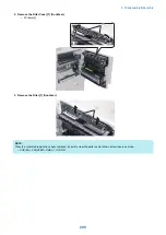
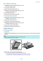
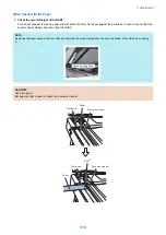
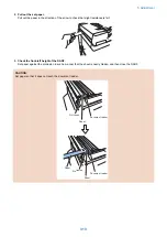
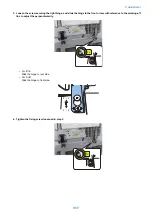
■ Hinge pressure adjustment
1. Open the ADF, and find out the lowest position it stays open without holding it by hands.
2. Find out if the height of the position checked in step 1 is within the standard range.
Standard range: 19 cm or more
5. Adjustment
309
Summary of Contents for imagerunner advance 4551i
Page 19: ...Product Overview 1 Product Lineup 7 Features 13 Specifications 16 Name of Parts 26 ...
Page 155: ...Periodical Service 3 Consumable Parts List 143 Cleaning Check Adjustment Locations 146 ...
Page 392: ...Error Jam Alarm 7 Overview 380 Error Code 383 Jam Code 509 Alarm Code 520 ...
Page 545: ...Service Mode 8 Overview 533 COPIER 549 FEEDER 845 SORTER 851 BOARD 871 ...
Page 892: ...Unpacking 1 2 1200 mm 840 mm 769 mm 1230 mm 2430 mm 3 9 Installation 879 ...
Page 895: ...3 4 NOTE Keep the removed screws for relocating the host machine 2x 5 6 7 9 Installation 882 ...
Page 896: ...8 9 10 1x Installing the Air Filter 1 9 Installation 883 ...
Page 897: ...2 3 Installing the Drum Unit 1 2 3 9 Installation 884 ...
Page 899: ...8 NOTE The screw removed at procedure 4 is used 1x 9 10 11 12 9 Installation 886 ...
Page 923: ...5 6 NOTE Use the screws and Rubber Caps removed in step 1 2x 7 2x 9 Installation 910 ...
Page 935: ...7 1x 8 9 6x 10 2x 9 Installation 922 ...
Page 936: ...11 Installing the NFC Kit 1 2 2x 3 TP M3x4 1x 9 Installation 923 ...
Page 938: ...4 5 1x 6 9 Installation 925 ...
Page 985: ...8 2x 2x TP M4x8 Black When installing the USB Keyboard 1 9 Installation 972 ...
Page 991: ...7 4x 8 1x 1x Lower Cover 9 1x 10 1x 1x 9 Installation 978 ...
Page 992: ...11 1x 1x 12 1x 13 TP M3x12 2x 14 4x TP M3x6 9 Installation 979 ...
Page 997: ...Installation Procedure 1 2 2x 3 2x 4 6x 5 4x 9 Installation 984 ...
Page 998: ...6 7 NOTE Do not close the Wire Saddle 1x 1x 8 9 9 Installation 985 ...
Page 1003: ...2 1x 1x 3 2x 2x 4 9 Installation 990 ...
Page 1012: ...2 1x 1x 3 2x 2x 4 9 Installation 999 ...
Page 1014: ...7 CAUTION The connector must be contacted TP㸹M3x6 3x 1x 8 4x 9 9 Installation 1001 ...
Page 1016: ...13 4x 14 15 Binding M4x16 Binding M3x16 2x M3x16 M4x16 16 Binding M4x6 1x 9 Installation 1003 ...
Page 1023: ...Installation Procedure Preparation 1 4x 2 1x 1x 3 2x 9 Installation 1010 ...
Page 1029: ...4 5 1x 1x 9 Installation 1016 ...
Page 1048: ...3 2x TP M3x8 Black 4 2x TP M3x6 5 9 Installation 1035 ...
Page 1053: ... Installing the Removable HDD Kit 1 2x 2x 2 3 1x 4 9 Installation 1040 ...
Page 1065: ...3 2x TP M3x8 Black 4 2x TP M3x6 5 9 Installation 1052 ...
Page 1071: ... Installing the Removable HDD Kit 1 2x 2x 2 3 1x 4 9 Installation 1058 ...


