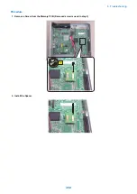


• When the overwriting setting is OFF
• Capturing is stopped.
• CAPSTATE of capturing becomes "HDDFULL". Note that STT-STP remains as start state (1). Capturing is started
again by changing the value from STT-STP (0) to STT-STP (1).
• If the HDDFULL state is cleared when starting capturing again, capturing is started.
• CAPSTATE of capturing becomes "RUNNING".
• If the HDDFULL state is not cleared, starting data capturing results in an error.
• CAPSTATE of capturing remains as "HDDFULL".
• When a command of stopping data capturing is given during the "HDDFULL" state, CAPSTATE of capturing
remains as "STOP".
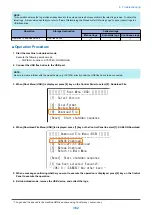
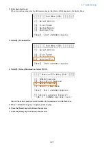
● Procedure for Setting the Encryption Function
1. Set "2" in the following service mode to enable this function.
• (Level2) COPIER > Test > NET-CAP > ENCDATA
0: Data is encrypted at data extraction (factory setting value).
1: Data is not encrypted at data extraction.
2: Two types of files (one in encrypted format and another in clear text format) are extracted at data extraction.
When the encryption setting is enabled, the extension of the extracted packet data is XXX.can.
When the encryption setting is disabled, the extension of the extracted packet data is XXX.cap.
This setting applies only when using USB memory device for data extraction.
NOTE:
When collecting data using SST, the above service mode setting is not reflected and both files in encrypted format and clear text
format are always collected.
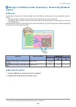
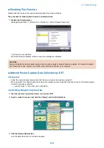
● Procedure for Setting the Payload Drop Function
1. Set "1" in the following service mode to enable this setting.
• (Level2) COPIER > Test > NET-CAP > PAYLOAD
0: Payload is not discarded (factory setting value)
1: Payload is discarded
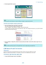
The obtained packet data includes a header part and data part. The header part includes data such as the TCP header and
IP header. The data part includes the actual data.
Enabling this function discards the actual payload data and extracts only the data from the header part, which has the following
effects.
• Can be used when customer data is not allowed to be extracted
• Can be used in an environment where traffic is highly overloaded
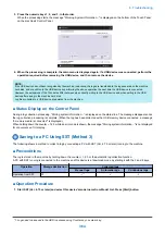
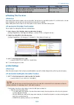
Image chart of packet data structure
Header part
Data part
Discarded part
● Procedure for Setting the Filter Function
1. Set "1" in the following service mode to enable this function.
• (Level2) COPIER > Test > NET-CAP > SIMPFILT
0: Filtering is not performed. All the data is collected (factory default setting).
1: Filtering is performed.
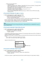
If this function is enabled, only packet data that includes the machine's MAC address in the packet header is captured.
6. Troubleshooting
373
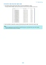
Summary of Contents for imagerunner advance 4551i
Page 19: ...Product Overview 1 Product Lineup 7 Features 13 Specifications 16 Name of Parts 26 ...
Page 155: ...Periodical Service 3 Consumable Parts List 143 Cleaning Check Adjustment Locations 146 ...
Page 392: ...Error Jam Alarm 7 Overview 380 Error Code 383 Jam Code 509 Alarm Code 520 ...
Page 545: ...Service Mode 8 Overview 533 COPIER 549 FEEDER 845 SORTER 851 BOARD 871 ...
Page 892: ...Unpacking 1 2 1200 mm 840 mm 769 mm 1230 mm 2430 mm 3 9 Installation 879 ...
Page 895: ...3 4 NOTE Keep the removed screws for relocating the host machine 2x 5 6 7 9 Installation 882 ...
Page 896: ...8 9 10 1x Installing the Air Filter 1 9 Installation 883 ...
Page 897: ...2 3 Installing the Drum Unit 1 2 3 9 Installation 884 ...
Page 899: ...8 NOTE The screw removed at procedure 4 is used 1x 9 10 11 12 9 Installation 886 ...
Page 923: ...5 6 NOTE Use the screws and Rubber Caps removed in step 1 2x 7 2x 9 Installation 910 ...
Page 935: ...7 1x 8 9 6x 10 2x 9 Installation 922 ...
Page 936: ...11 Installing the NFC Kit 1 2 2x 3 TP M3x4 1x 9 Installation 923 ...
Page 938: ...4 5 1x 6 9 Installation 925 ...
Page 985: ...8 2x 2x TP M4x8 Black When installing the USB Keyboard 1 9 Installation 972 ...
Page 991: ...7 4x 8 1x 1x Lower Cover 9 1x 10 1x 1x 9 Installation 978 ...
Page 992: ...11 1x 1x 12 1x 13 TP M3x12 2x 14 4x TP M3x6 9 Installation 979 ...
Page 997: ...Installation Procedure 1 2 2x 3 2x 4 6x 5 4x 9 Installation 984 ...
Page 998: ...6 7 NOTE Do not close the Wire Saddle 1x 1x 8 9 9 Installation 985 ...
Page 1003: ...2 1x 1x 3 2x 2x 4 9 Installation 990 ...
Page 1012: ...2 1x 1x 3 2x 2x 4 9 Installation 999 ...
Page 1014: ...7 CAUTION The connector must be contacted TP㸹M3x6 3x 1x 8 4x 9 9 Installation 1001 ...
Page 1016: ...13 4x 14 15 Binding M4x16 Binding M3x16 2x M3x16 M4x16 16 Binding M4x6 1x 9 Installation 1003 ...
Page 1023: ...Installation Procedure Preparation 1 4x 2 1x 1x 3 2x 9 Installation 1010 ...
Page 1029: ...4 5 1x 1x 9 Installation 1016 ...
Page 1048: ...3 2x TP M3x8 Black 4 2x TP M3x6 5 9 Installation 1035 ...
Page 1053: ... Installing the Removable HDD Kit 1 2x 2x 2 3 1x 4 9 Installation 1040 ...
Page 1065: ...3 2x TP M3x8 Black 4 2x TP M3x6 5 9 Installation 1052 ...
Page 1071: ... Installing the Removable HDD Kit 1 2x 2x 2 3 1x 4 9 Installation 1058 ...


