


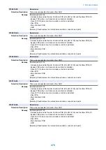


674-0301-07
Fax configuration error
Detection Description
It was detected that there was no 1-line Fax Board installed while the IP Fax license was enabled.
Remedy
1. Install the Fax Board (1-line) to use the machine as an IP Fax model.
2. Uninstall the IP Fax license and install the G3 Fax Board to use the machine as a G3 Fax
model.S15
677-0001-00
Print server error
Detection Description
Abnormality detected on the exhaust fan operation of printer server
Remedy
1. Check supplying power to the exhaust fan
2. Exhaust fan replacement
677-0003-00
Print server error
Detection Description
An error in the fan of the Print Server was detected.
Remedy
[Related parts] R1.00
- Print Server Fan
- Main Controller PCB
[Remedy] Check/replace the related harness/cable, connector and parts.
677-0004-00
Print server error
Detection Description
Abnormality detected on the CPU fan operation of printer server
Remedy
1. Check supplying power to the CPU fan
2. CPU fan replacement
677-0010-00
Print server error
Detection Description
Failure was detected in operation of the CPU fan on the print server.
Remedy
1. Replace the board of the print server.
2. Reinstall the Print Server (For details, refer to "Service Manual image PASS P2.")
677-0080-00
Print server error
Detection Description
Error is detected at the Mother Board check when print server is started.
Remedy
1. Check the cable connection and turn OFF and then ON the power.
2. Reinstall the print server (For details, refer to "Service Manual image PASS P2.")
711-0001-05
UFDI communication error
Detection Description
Communication system error (reception time out error/checksum error etc.)
Remedy
[Related parts]
- Harness connecting from the DC Controller PCB (UN2) to the Finisher Controller PCB. (PCB1/
PCB101)
- Finisher Controller PCB (PCB1/PCB101)
- DC Controller PCB (UN2)
[Remedy]
1.Check/replace the related harness/cable, connector and parts.
2.Replace the Finisher Controller PCB.
3.Replace the DC Controller PCB.
[Reference]
Before replacing the DC Controller PCB, back up the service mode data and restore the backup
data after the replacement so the data may be able to be protected.
- Backup: COPIER (LEVEL2)> FUNCTION> SYSTEM> DSRAMBUP
- Restoration: COPIER (LEVEL2)> FUNCTION> SYSTEM> DSRAMRES
7. Error/Jam/Alarm
462
Summary of Contents for imagerunner advance 4551i
Page 19: ...Product Overview 1 Product Lineup 7 Features 13 Specifications 16 Name of Parts 26 ...
Page 155: ...Periodical Service 3 Consumable Parts List 143 Cleaning Check Adjustment Locations 146 ...
Page 392: ...Error Jam Alarm 7 Overview 380 Error Code 383 Jam Code 509 Alarm Code 520 ...
Page 545: ...Service Mode 8 Overview 533 COPIER 549 FEEDER 845 SORTER 851 BOARD 871 ...
Page 892: ...Unpacking 1 2 1200 mm 840 mm 769 mm 1230 mm 2430 mm 3 9 Installation 879 ...
Page 895: ...3 4 NOTE Keep the removed screws for relocating the host machine 2x 5 6 7 9 Installation 882 ...
Page 896: ...8 9 10 1x Installing the Air Filter 1 9 Installation 883 ...
Page 897: ...2 3 Installing the Drum Unit 1 2 3 9 Installation 884 ...
Page 899: ...8 NOTE The screw removed at procedure 4 is used 1x 9 10 11 12 9 Installation 886 ...
Page 923: ...5 6 NOTE Use the screws and Rubber Caps removed in step 1 2x 7 2x 9 Installation 910 ...
Page 935: ...7 1x 8 9 6x 10 2x 9 Installation 922 ...
Page 936: ...11 Installing the NFC Kit 1 2 2x 3 TP M3x4 1x 9 Installation 923 ...
Page 938: ...4 5 1x 6 9 Installation 925 ...
Page 985: ...8 2x 2x TP M4x8 Black When installing the USB Keyboard 1 9 Installation 972 ...
Page 991: ...7 4x 8 1x 1x Lower Cover 9 1x 10 1x 1x 9 Installation 978 ...
Page 992: ...11 1x 1x 12 1x 13 TP M3x12 2x 14 4x TP M3x6 9 Installation 979 ...
Page 997: ...Installation Procedure 1 2 2x 3 2x 4 6x 5 4x 9 Installation 984 ...
Page 998: ...6 7 NOTE Do not close the Wire Saddle 1x 1x 8 9 9 Installation 985 ...
Page 1003: ...2 1x 1x 3 2x 2x 4 9 Installation 990 ...
Page 1012: ...2 1x 1x 3 2x 2x 4 9 Installation 999 ...
Page 1014: ...7 CAUTION The connector must be contacted TP㸹M3x6 3x 1x 8 4x 9 9 Installation 1001 ...
Page 1016: ...13 4x 14 15 Binding M4x16 Binding M3x16 2x M3x16 M4x16 16 Binding M4x6 1x 9 Installation 1003 ...
Page 1023: ...Installation Procedure Preparation 1 4x 2 1x 1x 3 2x 9 Installation 1010 ...
Page 1029: ...4 5 1x 1x 9 Installation 1016 ...
Page 1048: ...3 2x TP M3x8 Black 4 2x TP M3x6 5 9 Installation 1035 ...
Page 1053: ... Installing the Removable HDD Kit 1 2x 2x 2 3 1x 4 9 Installation 1040 ...
Page 1065: ...3 2x TP M3x8 Black 4 2x TP M3x6 5 9 Installation 1052 ...
Page 1071: ... Installing the Removable HDD Kit 1 2x 2x 2 3 1x 4 9 Installation 1058 ...


