


04-1539
-
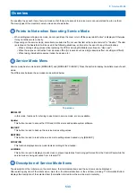
Paper Surface Sensor alarm
A. Operation / B. Cause /
C. Remedy
Cause:
- Deck Lifter Motor alarm
- The lifter cannot be raised.
Detection condition/timing: The Paper Surface Sensor was not turned ON within the specified
period of time when raising the lifter.
Movement/symptom:
While failure has occurred (an alarm has occurred), the target paper source cannot be used
because it is in no paper state.
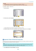
Measures:
- Forcibly open the receptacle.
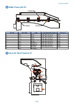
- Check that the Lifter Plate is not caught by the Side Guide.
- Remove the Front Cover, and check that the lifter wire is properly installed (no coming off,
disconnection, slack, or winding in the reverse direction).
- Remove the Deck Right Cover.
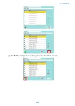
- Execute service mode: COPIER>FUNCTION>CLEAR>DK-RCV.
- Close the receptacle, and check if the Lifter Plate is raised from the right side.
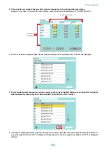
1) If it is not raised:
- If it is not raised and no motor drive sound is heard, check for improper connection of the connector
of the Relay PCB and the Paper Surface Sensor (PS6).
- If it is not operated after checking the connector connection, replace the Paper Surface Sensor
(PS6), the Relay PCB, and the Lifter Motor in that order.
2) If it is raised:
- Check if the Lifter Plate stops at the upper limit position.
- Check for improper connection of the Paper Surface Sensor (PS6).
- Check for any foreign matters on the bottom of the receptacle.
- Replace the Bottom Sensor (PS9) and the Lower Limit Switch 3.
04-1542
-
Lifter upper limit alarm
A. Operation / B. Cause /
C. Remedy
Cause:
Deck Lifter upper limit detection alarm
Detection condition/timing: The Upper Limit Sensor was turned ON while raising the lifter.
Movement/symptom:
While failure has occurred (an alarm has occurred), the target paper source cannot be used
because it is in no paper state.
Measures:
- Check the position of the Lifter Plate.
- Check for any improper connection, caught harness and disconnection of the Upper Limit Sensor
1 and 2 (PS4 and PS3).
- Execute service mode: COPIER>FUNCTION>CLEAR>DK-RCV, and check if the machine is
recovered.
- If the machine is not recovered, replace the Upper Limit Sensor 1 and 2 (PS4 and PS3).
04-1543
-
Lifter lower limit alarm
A. Operation / B. Cause /
C. Remedy
Cause:
Deck Lifter lower limit detection alarm
Detection condition/timing: The Lower Limit Detection Switch was turned ON while lowering the
lifter.
Movement/symptom:
While failure has occurred (an alarm has occurred), the target paper source cannot be used
because it is in no paper state.
Measures:
- Check the position of the Lifter Plate.
- Check for any improper connection, caught harness and disconnection of the Bottom Sensor
(PS9) and the Lower Limit Detection Switch (SW3).
- Execute service mode: COPIER>FUNCTION>CLEAR>DK-RCV, and check if the machine is
recovered.
- If the machine is not recovered, replace the Bottom Sensor (PS9) and the Lower Limit Detection
Switch (SW3).
7. Error/Jam/Alarm
522
Summary of Contents for imagerunner advance 4551i
Page 19: ...Product Overview 1 Product Lineup 7 Features 13 Specifications 16 Name of Parts 26 ...
Page 155: ...Periodical Service 3 Consumable Parts List 143 Cleaning Check Adjustment Locations 146 ...
Page 392: ...Error Jam Alarm 7 Overview 380 Error Code 383 Jam Code 509 Alarm Code 520 ...
Page 545: ...Service Mode 8 Overview 533 COPIER 549 FEEDER 845 SORTER 851 BOARD 871 ...
Page 892: ...Unpacking 1 2 1200 mm 840 mm 769 mm 1230 mm 2430 mm 3 9 Installation 879 ...
Page 895: ...3 4 NOTE Keep the removed screws for relocating the host machine 2x 5 6 7 9 Installation 882 ...
Page 896: ...8 9 10 1x Installing the Air Filter 1 9 Installation 883 ...
Page 897: ...2 3 Installing the Drum Unit 1 2 3 9 Installation 884 ...
Page 899: ...8 NOTE The screw removed at procedure 4 is used 1x 9 10 11 12 9 Installation 886 ...
Page 923: ...5 6 NOTE Use the screws and Rubber Caps removed in step 1 2x 7 2x 9 Installation 910 ...
Page 935: ...7 1x 8 9 6x 10 2x 9 Installation 922 ...
Page 936: ...11 Installing the NFC Kit 1 2 2x 3 TP M3x4 1x 9 Installation 923 ...
Page 938: ...4 5 1x 6 9 Installation 925 ...
Page 985: ...8 2x 2x TP M4x8 Black When installing the USB Keyboard 1 9 Installation 972 ...
Page 991: ...7 4x 8 1x 1x Lower Cover 9 1x 10 1x 1x 9 Installation 978 ...
Page 992: ...11 1x 1x 12 1x 13 TP M3x12 2x 14 4x TP M3x6 9 Installation 979 ...
Page 997: ...Installation Procedure 1 2 2x 3 2x 4 6x 5 4x 9 Installation 984 ...
Page 998: ...6 7 NOTE Do not close the Wire Saddle 1x 1x 8 9 9 Installation 985 ...
Page 1003: ...2 1x 1x 3 2x 2x 4 9 Installation 990 ...
Page 1012: ...2 1x 1x 3 2x 2x 4 9 Installation 999 ...
Page 1014: ...7 CAUTION The connector must be contacted TP㸹M3x6 3x 1x 8 4x 9 9 Installation 1001 ...
Page 1016: ...13 4x 14 15 Binding M4x16 Binding M3x16 2x M3x16 M4x16 16 Binding M4x6 1x 9 Installation 1003 ...
Page 1023: ...Installation Procedure Preparation 1 4x 2 1x 1x 3 2x 9 Installation 1010 ...
Page 1029: ...4 5 1x 1x 9 Installation 1016 ...
Page 1048: ...3 2x TP M3x8 Black 4 2x TP M3x6 5 9 Installation 1035 ...
Page 1053: ... Installing the Removable HDD Kit 1 2x 2x 2 3 1x 4 9 Installation 1040 ...
Page 1065: ...3 2x TP M3x8 Black 4 2x TP M3x6 5 9 Installation 1052 ...
Page 1071: ... Installing the Removable HDD Kit 1 2x 2x 2 3 1x 4 9 Installation 1058 ...


