


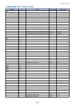

COPIER > DISPLAY > ANALOG
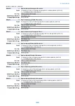
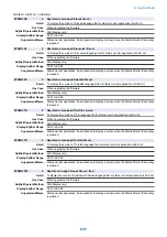
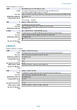
ABS-HUM
1
Display of inside moisture content
Detail
To display the absolute moisture content inside the machine detected by Environment Sensor.
Use Case
When checking the moisture content inside the machine
Adj/Set/Operate Method
N/A (Display only)
Display/Adj/Set Range
0 to 100
Unit
g
Appropriate Target Value
0 - 22
Related Service Mode
COPIER> DISPLAY> ANALOG> TEMP, HUM
Amount of Change per
Unit
1
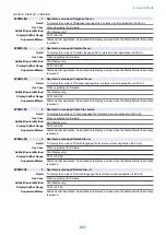
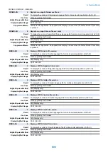
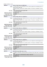
FIX-C
1
Display of Fixing Roller center temp
Detail
To display the center temperature of the Fixing Roller detected by the Fixing Main Thermistor.
Use Case
When checking the temperature at the center of Fixing Roller
Adj/Set/Operate Method
N/A (Display only)
Display/Adj/Set Range
0 to 999
Unit
deg C
Amount of Change per
Unit
1
FIX-E
1
Display of Fixing Roller edge temp
Detail
To display the edge temperature of the Fixing Roller detected by the Fixing Sub Thermistor 1.
Fixing Sub Thermistor 1 is located in the rear nip inlet side of Fixing Roller.
Use Case
When checking the edge temperature of the Fixing Roller
Adj/Set/Operate Method
N/A (Display only)
Display/Adj/Set Range
0 to 999
Unit
deg C
Amount of Change per
Unit
1
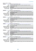
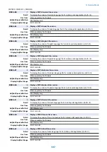
FIX-UE2
1
Display of Fixing Roller edge temp 2
Detail
To display the edge temperature of the Fixing Roller detected by the Fixing Sub Thermistor 2.
Fixing Sub Thermistor 2 is located in the rear nip inlet side of Fixing Roller.
Use Case
When checking the edge temperature of the Fixing Roller
Adj/Set/Operate Method
N/A (Display only)
Display/Adj/Set Range
0 to 999
Unit
deg C
Amount of Change per
Unit
1
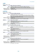
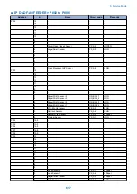
■ CST-STS
COPIER > DISPLAY > CST-STS
WIDTH-MF
2
Display of MP Tray paper width size
Detail
To display the paper width size set on the Multi-purpose Tray.
Use Case
When checking the paper width side set on the Multi-purpose Tray
Adj/Set/Operate Method
N/A (Display only)
Unit
mm
Amount of Change per
Unit
1
8. Service Mode
613
Summary of Contents for imagerunner advance 4551i
Page 19: ...Product Overview 1 Product Lineup 7 Features 13 Specifications 16 Name of Parts 26 ...
Page 155: ...Periodical Service 3 Consumable Parts List 143 Cleaning Check Adjustment Locations 146 ...
Page 392: ...Error Jam Alarm 7 Overview 380 Error Code 383 Jam Code 509 Alarm Code 520 ...
Page 545: ...Service Mode 8 Overview 533 COPIER 549 FEEDER 845 SORTER 851 BOARD 871 ...
Page 892: ...Unpacking 1 2 1200 mm 840 mm 769 mm 1230 mm 2430 mm 3 9 Installation 879 ...
Page 895: ...3 4 NOTE Keep the removed screws for relocating the host machine 2x 5 6 7 9 Installation 882 ...
Page 896: ...8 9 10 1x Installing the Air Filter 1 9 Installation 883 ...
Page 897: ...2 3 Installing the Drum Unit 1 2 3 9 Installation 884 ...
Page 899: ...8 NOTE The screw removed at procedure 4 is used 1x 9 10 11 12 9 Installation 886 ...
Page 923: ...5 6 NOTE Use the screws and Rubber Caps removed in step 1 2x 7 2x 9 Installation 910 ...
Page 935: ...7 1x 8 9 6x 10 2x 9 Installation 922 ...
Page 936: ...11 Installing the NFC Kit 1 2 2x 3 TP M3x4 1x 9 Installation 923 ...
Page 938: ...4 5 1x 6 9 Installation 925 ...
Page 985: ...8 2x 2x TP M4x8 Black When installing the USB Keyboard 1 9 Installation 972 ...
Page 991: ...7 4x 8 1x 1x Lower Cover 9 1x 10 1x 1x 9 Installation 978 ...
Page 992: ...11 1x 1x 12 1x 13 TP M3x12 2x 14 4x TP M3x6 9 Installation 979 ...
Page 997: ...Installation Procedure 1 2 2x 3 2x 4 6x 5 4x 9 Installation 984 ...
Page 998: ...6 7 NOTE Do not close the Wire Saddle 1x 1x 8 9 9 Installation 985 ...
Page 1003: ...2 1x 1x 3 2x 2x 4 9 Installation 990 ...
Page 1012: ...2 1x 1x 3 2x 2x 4 9 Installation 999 ...
Page 1014: ...7 CAUTION The connector must be contacted TP㸹M3x6 3x 1x 8 4x 9 9 Installation 1001 ...
Page 1016: ...13 4x 14 15 Binding M4x16 Binding M3x16 2x M3x16 M4x16 16 Binding M4x6 1x 9 Installation 1003 ...
Page 1023: ...Installation Procedure Preparation 1 4x 2 1x 1x 3 2x 9 Installation 1010 ...
Page 1029: ...4 5 1x 1x 9 Installation 1016 ...
Page 1048: ...3 2x TP M3x8 Black 4 2x TP M3x6 5 9 Installation 1035 ...
Page 1053: ... Installing the Removable HDD Kit 1 2x 2x 2 3 1x 4 9 Installation 1040 ...
Page 1065: ...3 2x TP M3x8 Black 4 2x TP M3x6 5 9 Installation 1052 ...
Page 1071: ... Installing the Removable HDD Kit 1 2x 2x 2 3 1x 4 9 Installation 1058 ...


