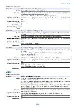


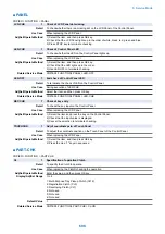

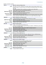

■ PANEL
COPIER > FUNCTION > PANEL
LCD-CHK
1
Check of LCD Panel dot missing
Detail
To check whether there is a missing dot on the LCD Panel of the Control Panel.
Use Case
When replacing the LCD Panel
Adj/Set/Operate Method
1) Select the item, and then press OK key.
2) Check that the LCD Panel lights up in the order of white, black, red, green and blue.
3) Press STOP key to terminate checking.
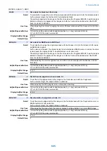
LED-CHK
1
Check of Control Panel LED
Detail
To check whether the LED on the Control Panel lights up.
Use Case
When replacing the LCD Panel
Adj/Set/Operate Method
1) Select the item, and then press OK key.
2) Check that the LED lights up in the order.
3) Use LED-OFF to terminate checking.
Related Service Mode
COPIER> FUNCTION> PANEL> LED-OFF
LED-OFF
1
End check of Control Panel LED
Detail
To terminate the check of LED on the Control Panel.
Use Case
During execution of LED-CHK
Adj/Set/Operate Method
Select the item, and then press OK key.
Related Service Mode
COPIER> FUNCTION> PANEL> LED-CHK
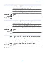
KEY-CHK
1
Check of key entry
Detail
To check the key input on the Control Panel.
Use Case
When replacing the LCD Panel
Adj/Set/Operate Method
1) Select the item and press the key on the Control Panel.
2) Check that the input value is displayed.
3) Cancel the selection to terminate checking.
TOUCHCHK
1
Adj of coordinate pstn of Touch Panel
Detail
To adjust the coordinate position on the Touch Panel of the Control Panel.
Use Case
When replacing the LCD Panel
Adj/Set/Operate Method
1) Select the item, and then press OK key.
2) Press the nine "+" keys in sequence.
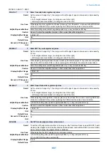
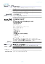
■ PART-CHK
COPIER > FUNCTION > PART-CHK
CL
1
Specification of operation Clutch
Detail
To specify the Clutch to operate.
Use Case
When replacing the Clutch/checking the operation
Adj/Set/Operate Method
Enter the value, and then press OK key.
Display/Adj/Set Range
1 to 6
1: Multi-Purpose Tray Pickup Clutch (CL12)
2: Registration Clutch (CL3)
3: Developing Clutch (CL1)
4: Not used
5: Not used
6: Not used
Default Value
1
Related Service Mode
COPIER> FUNCTION> PART-CHK> CL-ON
8. Service Mode
698
Summary of Contents for imagerunner advance 4551i
Page 19: ...Product Overview 1 Product Lineup 7 Features 13 Specifications 16 Name of Parts 26 ...
Page 155: ...Periodical Service 3 Consumable Parts List 143 Cleaning Check Adjustment Locations 146 ...
Page 392: ...Error Jam Alarm 7 Overview 380 Error Code 383 Jam Code 509 Alarm Code 520 ...
Page 545: ...Service Mode 8 Overview 533 COPIER 549 FEEDER 845 SORTER 851 BOARD 871 ...
Page 892: ...Unpacking 1 2 1200 mm 840 mm 769 mm 1230 mm 2430 mm 3 9 Installation 879 ...
Page 895: ...3 4 NOTE Keep the removed screws for relocating the host machine 2x 5 6 7 9 Installation 882 ...
Page 896: ...8 9 10 1x Installing the Air Filter 1 9 Installation 883 ...
Page 897: ...2 3 Installing the Drum Unit 1 2 3 9 Installation 884 ...
Page 899: ...8 NOTE The screw removed at procedure 4 is used 1x 9 10 11 12 9 Installation 886 ...
Page 923: ...5 6 NOTE Use the screws and Rubber Caps removed in step 1 2x 7 2x 9 Installation 910 ...
Page 935: ...7 1x 8 9 6x 10 2x 9 Installation 922 ...
Page 936: ...11 Installing the NFC Kit 1 2 2x 3 TP M3x4 1x 9 Installation 923 ...
Page 938: ...4 5 1x 6 9 Installation 925 ...
Page 985: ...8 2x 2x TP M4x8 Black When installing the USB Keyboard 1 9 Installation 972 ...
Page 991: ...7 4x 8 1x 1x Lower Cover 9 1x 10 1x 1x 9 Installation 978 ...
Page 992: ...11 1x 1x 12 1x 13 TP M3x12 2x 14 4x TP M3x6 9 Installation 979 ...
Page 997: ...Installation Procedure 1 2 2x 3 2x 4 6x 5 4x 9 Installation 984 ...
Page 998: ...6 7 NOTE Do not close the Wire Saddle 1x 1x 8 9 9 Installation 985 ...
Page 1003: ...2 1x 1x 3 2x 2x 4 9 Installation 990 ...
Page 1012: ...2 1x 1x 3 2x 2x 4 9 Installation 999 ...
Page 1014: ...7 CAUTION The connector must be contacted TP㸹M3x6 3x 1x 8 4x 9 9 Installation 1001 ...
Page 1016: ...13 4x 14 15 Binding M4x16 Binding M3x16 2x M3x16 M4x16 16 Binding M4x6 1x 9 Installation 1003 ...
Page 1023: ...Installation Procedure Preparation 1 4x 2 1x 1x 3 2x 9 Installation 1010 ...
Page 1029: ...4 5 1x 1x 9 Installation 1016 ...
Page 1048: ...3 2x TP M3x8 Black 4 2x TP M3x6 5 9 Installation 1035 ...
Page 1053: ... Installing the Removable HDD Kit 1 2x 2x 2 3 1x 4 9 Installation 1040 ...
Page 1065: ...3 2x TP M3x8 Black 4 2x TP M3x6 5 9 Installation 1052 ...
Page 1071: ... Installing the Removable HDD Kit 1 2x 2x 2 3 1x 4 9 Installation 1058 ...


