


COPIER > FUNCTION > SYSTEM
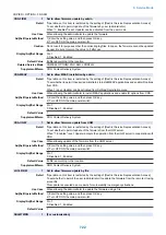
HD-CLEAR
1
Initialization of specified partition
Detail
*Operation on this item is restricted by the setting of [Restrict Service Representation Access].
To initialize the partition specified by CHK-TYPE at next startup.
Use Case
When E602/E614 error (file corruption, etc.) occurs
Adj/Set/Operate Method
Enter 1, and then press OK key.
Caution
Be sure to execute this item after CHK-TYPE.
Display/Adj/Set Range
0 to 1
0: Not executed, 1: Executed at next startup
Related Service Mode
COPIER> FUNCTION> SYSTEM> CHK-TYPE
DSRAMBUP
2
Backup of DC Controller PCB SRAM
Detail
To back up the setting data in SRAM of the DC Controller PCB.
Use Case
When replacing the DC Controller PCB for troubleshooting at the time of trouble occurrence
Adj/Set/Operate Method
Select the item, and then press OK key.
Caution
During operation, the setting data changes by manual or automatic adjustment. When backup data
which has been left for a long period of time is restored, it is overwritten with new setting data and
the old data is deleted.
Related Service Mode
COPIER> FUNCTION> SYSTEM> DSRAMRES
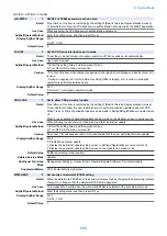
DSRAMRES
2
Restore of DC Controller PCB SRAM
Detail
To restore the setting data which has been backed up in SRAM of the DC Controller PCB.
Use Case
When replacing the DC Controller PCB for troubleshooting at the time of trouble occurrence
Adj/Set/Operate Method
Select the item, and then press OK key.
Caution
During operation, the setting data changes by manual or automatic adjustment. When backup data
which has been left for a long period of time is restored, it is overwritten with new setting data and
the old data is deleted.
Related Service Mode
COPIER> FUNCTION> SYSTEM> DSRAMBUP
RSRAMBUP
2
Backup of Reader Controller PCB SRAM
Detail
To back up the setting data in SRAM of the Reader Controller PCB.
Use Case
When replacing the Reader Controller PCB for troubleshooting at the time of trouble occurrence
Adj/Set/Operate Method
Select the item, and then press OK key.
Caution
During operation, the setting data changes by manual or automatic adjustment. When backup data
which has been left for a long period of time is restored, it is overwritten with new setting data and
the old data is deleted.
Related Service Mode
COPIER> FUNCTION> SYSTEM> RSRAMRES
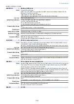
RSRAMRES
2
Restore of Reader Controller PCB SRAM
Detail
To restore the setting data which has been backed up in SRAM of the Reader Controller PCB.
Use Case
When replacing the Reader Controller PCB for troubleshooting at the time of trouble occurrence
Adj/Set/Operate Method
1) Select the item, and then press OK key.
2) Turn OFF/ON the main power switch.
Caution
During operation, the setting data changes by manual or automatic adjustment. When backup data
which has been left for a long period of time is restored, it is overwritten with new setting data and
the old data is deleted.
Related Service Mode
COPIER> FUNCTION> SYSTEM> RSRAMBUP
R-REBOOT
1
Reboot of host machine (Remote)
Detail
To reboot the host machine.
Use Case
When the reboot is carried out with the remote control by VNC
Adj/Set/Operate Method
Select the item, and then press OK key.
8. Service Mode
714
Summary of Contents for imagerunner advance 4551i
Page 19: ...Product Overview 1 Product Lineup 7 Features 13 Specifications 16 Name of Parts 26 ...
Page 155: ...Periodical Service 3 Consumable Parts List 143 Cleaning Check Adjustment Locations 146 ...
Page 392: ...Error Jam Alarm 7 Overview 380 Error Code 383 Jam Code 509 Alarm Code 520 ...
Page 545: ...Service Mode 8 Overview 533 COPIER 549 FEEDER 845 SORTER 851 BOARD 871 ...
Page 892: ...Unpacking 1 2 1200 mm 840 mm 769 mm 1230 mm 2430 mm 3 9 Installation 879 ...
Page 895: ...3 4 NOTE Keep the removed screws for relocating the host machine 2x 5 6 7 9 Installation 882 ...
Page 896: ...8 9 10 1x Installing the Air Filter 1 9 Installation 883 ...
Page 897: ...2 3 Installing the Drum Unit 1 2 3 9 Installation 884 ...
Page 899: ...8 NOTE The screw removed at procedure 4 is used 1x 9 10 11 12 9 Installation 886 ...
Page 923: ...5 6 NOTE Use the screws and Rubber Caps removed in step 1 2x 7 2x 9 Installation 910 ...
Page 935: ...7 1x 8 9 6x 10 2x 9 Installation 922 ...
Page 936: ...11 Installing the NFC Kit 1 2 2x 3 TP M3x4 1x 9 Installation 923 ...
Page 938: ...4 5 1x 6 9 Installation 925 ...
Page 985: ...8 2x 2x TP M4x8 Black When installing the USB Keyboard 1 9 Installation 972 ...
Page 991: ...7 4x 8 1x 1x Lower Cover 9 1x 10 1x 1x 9 Installation 978 ...
Page 992: ...11 1x 1x 12 1x 13 TP M3x12 2x 14 4x TP M3x6 9 Installation 979 ...
Page 997: ...Installation Procedure 1 2 2x 3 2x 4 6x 5 4x 9 Installation 984 ...
Page 998: ...6 7 NOTE Do not close the Wire Saddle 1x 1x 8 9 9 Installation 985 ...
Page 1003: ...2 1x 1x 3 2x 2x 4 9 Installation 990 ...
Page 1012: ...2 1x 1x 3 2x 2x 4 9 Installation 999 ...
Page 1014: ...7 CAUTION The connector must be contacted TP㸹M3x6 3x 1x 8 4x 9 9 Installation 1001 ...
Page 1016: ...13 4x 14 15 Binding M4x16 Binding M3x16 2x M3x16 M4x16 16 Binding M4x6 1x 9 Installation 1003 ...
Page 1023: ...Installation Procedure Preparation 1 4x 2 1x 1x 3 2x 9 Installation 1010 ...
Page 1029: ...4 5 1x 1x 9 Installation 1016 ...
Page 1048: ...3 2x TP M3x8 Black 4 2x TP M3x6 5 9 Installation 1035 ...
Page 1053: ... Installing the Removable HDD Kit 1 2x 2x 2 3 1x 4 9 Installation 1040 ...
Page 1065: ...3 2x TP M3x8 Black 4 2x TP M3x6 5 9 Installation 1052 ...
Page 1071: ... Installing the Removable HDD Kit 1 2x 2x 2 3 1x 4 9 Installation 1058 ...


