


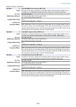


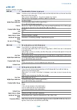


COPIER > OPTION > NETWORK
AFS-JOB
1
Set of FAX server job reception port
Detail
*Operation on this item is restricted by the setting of [Restrict Service Representation Access].
To set the reception port of the fax server to which a fax client sends jobs.
Use Case
When changing the job reception port of the fax server
Adj/Set/Operate Method
1) Enter the setting value, and then press OK key.
2) Turn OFF/ON the main power switch.
Display/Adj/Set Range
0 to 65535
Default Value
20317
Related Service Mode
COPIER> OPTION> NETWORK> AFC-EVNT
AFC-EVNT
1
Set of FAX client event reception port
Detail
*Operation on this item is restricted by the setting of [Restrict Service Representation Access].
To set the event notification reception port of a fax client.
Use Case
When changing the event notification reception port of a fax client
Adj/Set/Operate Method
1) Enter the setting value, and then press OK key.
2) Turn OFF/ON the main power switch.
Display/Adj/Set Range
0 to 65535
Default Value
29400
Related Service Mode
COPIER> OPTION> NETWORK> AFS-JOB
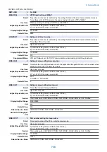
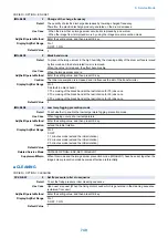
ILOGMODE
1
Setting of filter log target packet
Detail
*Operation on this item is restricted by the setting of [Restrict Service Representation Access].
To set the target packet to be recorded in the filter log.
Usually, only the unicast packets to the machine are recorded in the filter log by PFW (personal
firewall).
When 1 is set, address filter is enabled for all protocols so all packets are recorded in the filter log.
However, logs of multicast/broadcast packets sent from a harmless device or an address that are
subject to rejection and have no direct relation to the machine are also recorded, and consequently
the number of logs is increased.
Use Case
Upon user's request (to collect all filter logs)
Adj/Set/Operate Method
1) Enter the setting value, and then press OK key.
2) Turn OFF/ON the main power switch.
Caution
When 1 is set, the number of logs is increased because logs of packets which have no direct
relation to the machine are recorded.
Display/Adj/Set Range
0 to 1
0: Unicast packets to the machine only, 1: All packets
Default Value
0
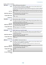
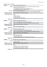
ILOGKEEP
1
Set of IP address block log hold time
Detail
*Operation on this item is restricted by the setting of [Restrict Service Representation Access].
To set the retention time from the log time of IP block.
When access is made again from a same IP address which was blocked before, if it is within the
retention time of the previous log, its log is not recorded.
If access is frequently made from a same IP address, the log record of the UI might be filled with
its logs. If the user considers that a single log for a same IP address is enough, set the longer
retention time.
Use Case
Upon user's request
Adj/Set/Operate Method
1) Enter the setting value, and then press OK key.
2) Turn OFF/ON the main power switch.
Display/Adj/Set Range
0 to 48
0: 1 minute (special mode)
1 to 48: 1 hour to 48 hours
Default Value
1
8. Service Mode
742
Summary of Contents for imagerunner advance 4551i
Page 19: ...Product Overview 1 Product Lineup 7 Features 13 Specifications 16 Name of Parts 26 ...
Page 155: ...Periodical Service 3 Consumable Parts List 143 Cleaning Check Adjustment Locations 146 ...
Page 392: ...Error Jam Alarm 7 Overview 380 Error Code 383 Jam Code 509 Alarm Code 520 ...
Page 545: ...Service Mode 8 Overview 533 COPIER 549 FEEDER 845 SORTER 851 BOARD 871 ...
Page 892: ...Unpacking 1 2 1200 mm 840 mm 769 mm 1230 mm 2430 mm 3 9 Installation 879 ...
Page 895: ...3 4 NOTE Keep the removed screws for relocating the host machine 2x 5 6 7 9 Installation 882 ...
Page 896: ...8 9 10 1x Installing the Air Filter 1 9 Installation 883 ...
Page 897: ...2 3 Installing the Drum Unit 1 2 3 9 Installation 884 ...
Page 899: ...8 NOTE The screw removed at procedure 4 is used 1x 9 10 11 12 9 Installation 886 ...
Page 923: ...5 6 NOTE Use the screws and Rubber Caps removed in step 1 2x 7 2x 9 Installation 910 ...
Page 935: ...7 1x 8 9 6x 10 2x 9 Installation 922 ...
Page 936: ...11 Installing the NFC Kit 1 2 2x 3 TP M3x4 1x 9 Installation 923 ...
Page 938: ...4 5 1x 6 9 Installation 925 ...
Page 985: ...8 2x 2x TP M4x8 Black When installing the USB Keyboard 1 9 Installation 972 ...
Page 991: ...7 4x 8 1x 1x Lower Cover 9 1x 10 1x 1x 9 Installation 978 ...
Page 992: ...11 1x 1x 12 1x 13 TP M3x12 2x 14 4x TP M3x6 9 Installation 979 ...
Page 997: ...Installation Procedure 1 2 2x 3 2x 4 6x 5 4x 9 Installation 984 ...
Page 998: ...6 7 NOTE Do not close the Wire Saddle 1x 1x 8 9 9 Installation 985 ...
Page 1003: ...2 1x 1x 3 2x 2x 4 9 Installation 990 ...
Page 1012: ...2 1x 1x 3 2x 2x 4 9 Installation 999 ...
Page 1014: ...7 CAUTION The connector must be contacted TP㸹M3x6 3x 1x 8 4x 9 9 Installation 1001 ...
Page 1016: ...13 4x 14 15 Binding M4x16 Binding M3x16 2x M3x16 M4x16 16 Binding M4x6 1x 9 Installation 1003 ...
Page 1023: ...Installation Procedure Preparation 1 4x 2 1x 1x 3 2x 9 Installation 1010 ...
Page 1029: ...4 5 1x 1x 9 Installation 1016 ...
Page 1048: ...3 2x TP M3x8 Black 4 2x TP M3x6 5 9 Installation 1035 ...
Page 1053: ... Installing the Removable HDD Kit 1 2x 2x 2 3 1x 4 9 Installation 1040 ...
Page 1065: ...3 2x TP M3x8 Black 4 2x TP M3x6 5 9 Installation 1052 ...
Page 1071: ... Installing the Removable HDD Kit 1 2x 2x 2 3 1x 4 9 Installation 1058 ...


