


■ IMG-RDR
COPIER > OPTION > IMG-RDR
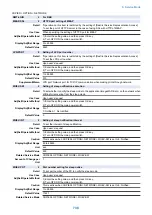
DFDST-L1
1
Adj img crrct level: stream read, front
Detail
To set whether to perform image correction between originals in the Scanner Unit (for front side)
at stream reading based on the result of dust detection.
- In the case of DADF (reverse model)
Increase the value when black lines appear. As the value is larger, the image is more likely to be
corrected because the machine is more likely to respond to small dust.
Decrease the value if a fine image portion is unclear as a result of dust detection correction control.
As the value is smaller, the image is less likely to be corrected because the machine is less likely
to respond to dust.
- In the case of DADF (1-path model)
Set one of 1 to 255 when black lines appear. Dust detection is performed and image is corrected
as needed.
Set 0 if a fine image portion is unclear as a result of dust detection correction control. In that case,
dust detection is not performed.
Use Case
- When black line occurs due to dust
- Upon user's request
Adj/Set/Operate Method
1) Enter the setting value, and then press OK key.
2) Turn OFF/ON the main power switch.
Caution
In the case of DADF (reverse model), a fine image portion may be unclear if the value is too large.
If the value is too small, black lines may appear on the image.
Display/Adj/Set Range
0 to 255
0: OFF
1 to 255: ON (DADF (1-path model) only)
Default Value
200
Related Service Mode
COPIER> OPTION> IMG-RDR> DFDST-L2
Supplement/Memo
Black lines may appear on the image if there is dust. With dust detection correction control, the
image is corrected to prevent black lines once dust is detected.
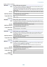
DFDST-L2
1
Adj dust dtct level: stream read, front
Detail
- In the case of DADF (reverse model)
To adjust dust detection level for dust avoidance control that is executed in the Scanner Unit (for
front side) after a stream reading job is completed.
- In the case of DADF (1-path model)
To adjust dust detection level for dust avoidance control that is executed in the Scanner Unit (for
front side) at start of the first stream reading after power-on.
Decrease the value in the case of frequent display of cleaning instruction at the time of dust
detection. As the value is smaller, dust is less likely to be detected. When 0 is set, the cleaning
instruction is not displayed.
Increase the value when black lines appear. As the value is larger, the small dust is more likely to
be detected.
Use Case
- When black line appears due to dust
- Upon user's request
Adj/Set/Operate Method
1) Enter the setting value, and then press OK key.
2) Turn OFF/ON the main power switch.
Caution
If the value is too large, the cleaning instruction screen may appear too often since even small dust
that will not appear on the image can be detected.
If the value is too small, black lines may appear on the image.
Display/Adj/Set Range
0 to 255
0: OFF
Default Value
200
Related Service Mode
COPIER> OPTION> IMG-RDR> DFDST-L1
Supplement/Memo
With the dust avoidance control, reading position is adjusted to minimize dust to be least detected.
The control is performed at start of the first job after power-on in the case of DADF (1-path model);
whereas it is performed every time a job is completed in the case of DADF (reverse model).
8. Service Mode
752
Summary of Contents for imagerunner advance 4551i
Page 19: ...Product Overview 1 Product Lineup 7 Features 13 Specifications 16 Name of Parts 26 ...
Page 155: ...Periodical Service 3 Consumable Parts List 143 Cleaning Check Adjustment Locations 146 ...
Page 392: ...Error Jam Alarm 7 Overview 380 Error Code 383 Jam Code 509 Alarm Code 520 ...
Page 545: ...Service Mode 8 Overview 533 COPIER 549 FEEDER 845 SORTER 851 BOARD 871 ...
Page 892: ...Unpacking 1 2 1200 mm 840 mm 769 mm 1230 mm 2430 mm 3 9 Installation 879 ...
Page 895: ...3 4 NOTE Keep the removed screws for relocating the host machine 2x 5 6 7 9 Installation 882 ...
Page 896: ...8 9 10 1x Installing the Air Filter 1 9 Installation 883 ...
Page 897: ...2 3 Installing the Drum Unit 1 2 3 9 Installation 884 ...
Page 899: ...8 NOTE The screw removed at procedure 4 is used 1x 9 10 11 12 9 Installation 886 ...
Page 923: ...5 6 NOTE Use the screws and Rubber Caps removed in step 1 2x 7 2x 9 Installation 910 ...
Page 935: ...7 1x 8 9 6x 10 2x 9 Installation 922 ...
Page 936: ...11 Installing the NFC Kit 1 2 2x 3 TP M3x4 1x 9 Installation 923 ...
Page 938: ...4 5 1x 6 9 Installation 925 ...
Page 985: ...8 2x 2x TP M4x8 Black When installing the USB Keyboard 1 9 Installation 972 ...
Page 991: ...7 4x 8 1x 1x Lower Cover 9 1x 10 1x 1x 9 Installation 978 ...
Page 992: ...11 1x 1x 12 1x 13 TP M3x12 2x 14 4x TP M3x6 9 Installation 979 ...
Page 997: ...Installation Procedure 1 2 2x 3 2x 4 6x 5 4x 9 Installation 984 ...
Page 998: ...6 7 NOTE Do not close the Wire Saddle 1x 1x 8 9 9 Installation 985 ...
Page 1003: ...2 1x 1x 3 2x 2x 4 9 Installation 990 ...
Page 1012: ...2 1x 1x 3 2x 2x 4 9 Installation 999 ...
Page 1014: ...7 CAUTION The connector must be contacted TP㸹M3x6 3x 1x 8 4x 9 9 Installation 1001 ...
Page 1016: ...13 4x 14 15 Binding M4x16 Binding M3x16 2x M3x16 M4x16 16 Binding M4x6 1x 9 Installation 1003 ...
Page 1023: ...Installation Procedure Preparation 1 4x 2 1x 1x 3 2x 9 Installation 1010 ...
Page 1029: ...4 5 1x 1x 9 Installation 1016 ...
Page 1048: ...3 2x TP M3x8 Black 4 2x TP M3x6 5 9 Installation 1035 ...
Page 1053: ... Installing the Removable HDD Kit 1 2x 2x 2 3 1x 4 9 Installation 1040 ...
Page 1065: ...3 2x TP M3x8 Black 4 2x TP M3x6 5 9 Installation 1052 ...
Page 1071: ... Installing the Removable HDD Kit 1 2x 2x 2 3 1x 4 9 Installation 1058 ...


