


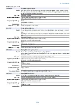


■ CUSTOM
COPIER > OPTION > CUSTOM
SC-L-CNT
1
Set large paper jdgmt reference at scan
Detail
To set the judgment reference of the scan counter as to which to use B4 or LTR to determine large
size.
The threshold is determined by the combination with the setting of B4-L-CNT.
SC-L-CNT=0, B4-L-CNT=0: paper exceeding B4 is determined as large size, paper with B4 or
smaller is determined as small size.
SC-L-CNT=0, B4-L-CNT=1: paper with B4 or larger is determined as large size, paper smaller than
B4 is determined as small size.
Use Case
As needed
Adj/Set/Operate Method
1) Enter the setting value, and then press OK key.
2) Turn OFF/ON the main power switch.
Display/Adj/Set Range
0 to 1
0: B4 size, 1: LTR size
Default Value
0
Related Service Mode
COPIER> OPTION> USER> B4-L-CNT
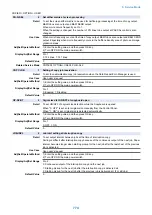
SCANTYPE
1
Switching of DADF + Reader type
Detail
To switch the type of DADF + Reader to a different type.
Use Case
At installation
Adj/Set/Operate Method
1) Enter the setting value, and then press OK key.
2) Turn OFF/ON the main power switch.
Display/Adj/Set Range
0 to 1
0: DADF (reverse model) + Reader, 1: DADF (1-path model) + Reader
Default Value
0
PDLEVCT1
2
Set event skipping at continuous PDL job
Detail
To set event skipping at continuous PDL job.
During continuous operation, processing performance may be decreased due to other events
generated by the event in operation. In this case, decrease of processing performance can be
prevented by skipping the amount of event.
Processing performance: No event skipping < Subject of skipping 1
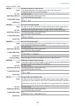
Use Case
Upon user's request
Adj/Set/Operate Method
1) Enter the setting value, and then press OK key.
2) Turn OFF/ON the main power switch.
Display/Adj/Set Range
0 to 1
0: No event skipping, 1: Subject of skipping 1
Default Value
1
ABK-TOOL
1
Allow access from address book mntc tool
Detail
*Operation on this item is restricted by the setting of [Restrict Service Representation Access].
To set whether to accept import from the address book maintenance tool.
Use Case
When executing import from the address book maintenance tool
Adj/Set/Operate Method
1) Enter the setting value, and then press OK key.
2) Turn OFF/ON the main power switch.
Display/Adj/Set Range
0 to 1
0: Disabled, 1: Enabled
Default Value
0
Supplement/Memo
Address book maintenance tool: Tool provided from CMJ.
8. Service Mode
764
Summary of Contents for imagerunner advance 4551i
Page 19: ...Product Overview 1 Product Lineup 7 Features 13 Specifications 16 Name of Parts 26 ...
Page 155: ...Periodical Service 3 Consumable Parts List 143 Cleaning Check Adjustment Locations 146 ...
Page 392: ...Error Jam Alarm 7 Overview 380 Error Code 383 Jam Code 509 Alarm Code 520 ...
Page 545: ...Service Mode 8 Overview 533 COPIER 549 FEEDER 845 SORTER 851 BOARD 871 ...
Page 892: ...Unpacking 1 2 1200 mm 840 mm 769 mm 1230 mm 2430 mm 3 9 Installation 879 ...
Page 895: ...3 4 NOTE Keep the removed screws for relocating the host machine 2x 5 6 7 9 Installation 882 ...
Page 896: ...8 9 10 1x Installing the Air Filter 1 9 Installation 883 ...
Page 897: ...2 3 Installing the Drum Unit 1 2 3 9 Installation 884 ...
Page 899: ...8 NOTE The screw removed at procedure 4 is used 1x 9 10 11 12 9 Installation 886 ...
Page 923: ...5 6 NOTE Use the screws and Rubber Caps removed in step 1 2x 7 2x 9 Installation 910 ...
Page 935: ...7 1x 8 9 6x 10 2x 9 Installation 922 ...
Page 936: ...11 Installing the NFC Kit 1 2 2x 3 TP M3x4 1x 9 Installation 923 ...
Page 938: ...4 5 1x 6 9 Installation 925 ...
Page 985: ...8 2x 2x TP M4x8 Black When installing the USB Keyboard 1 9 Installation 972 ...
Page 991: ...7 4x 8 1x 1x Lower Cover 9 1x 10 1x 1x 9 Installation 978 ...
Page 992: ...11 1x 1x 12 1x 13 TP M3x12 2x 14 4x TP M3x6 9 Installation 979 ...
Page 997: ...Installation Procedure 1 2 2x 3 2x 4 6x 5 4x 9 Installation 984 ...
Page 998: ...6 7 NOTE Do not close the Wire Saddle 1x 1x 8 9 9 Installation 985 ...
Page 1003: ...2 1x 1x 3 2x 2x 4 9 Installation 990 ...
Page 1012: ...2 1x 1x 3 2x 2x 4 9 Installation 999 ...
Page 1014: ...7 CAUTION The connector must be contacted TP㸹M3x6 3x 1x 8 4x 9 9 Installation 1001 ...
Page 1016: ...13 4x 14 15 Binding M4x16 Binding M3x16 2x M3x16 M4x16 16 Binding M4x6 1x 9 Installation 1003 ...
Page 1023: ...Installation Procedure Preparation 1 4x 2 1x 1x 3 2x 9 Installation 1010 ...
Page 1029: ...4 5 1x 1x 9 Installation 1016 ...
Page 1048: ...3 2x TP M3x8 Black 4 2x TP M3x6 5 9 Installation 1035 ...
Page 1053: ... Installing the Removable HDD Kit 1 2x 2x 2 3 1x 4 9 Installation 1040 ...
Page 1065: ...3 2x TP M3x8 Black 4 2x TP M3x6 5 9 Installation 1052 ...
Page 1071: ... Installing the Removable HDD Kit 1 2x 2x 2 3 1x 4 9 Installation 1058 ...


