

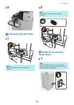


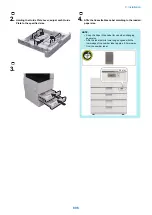
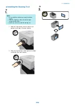
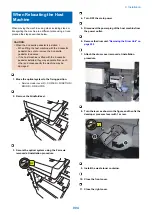


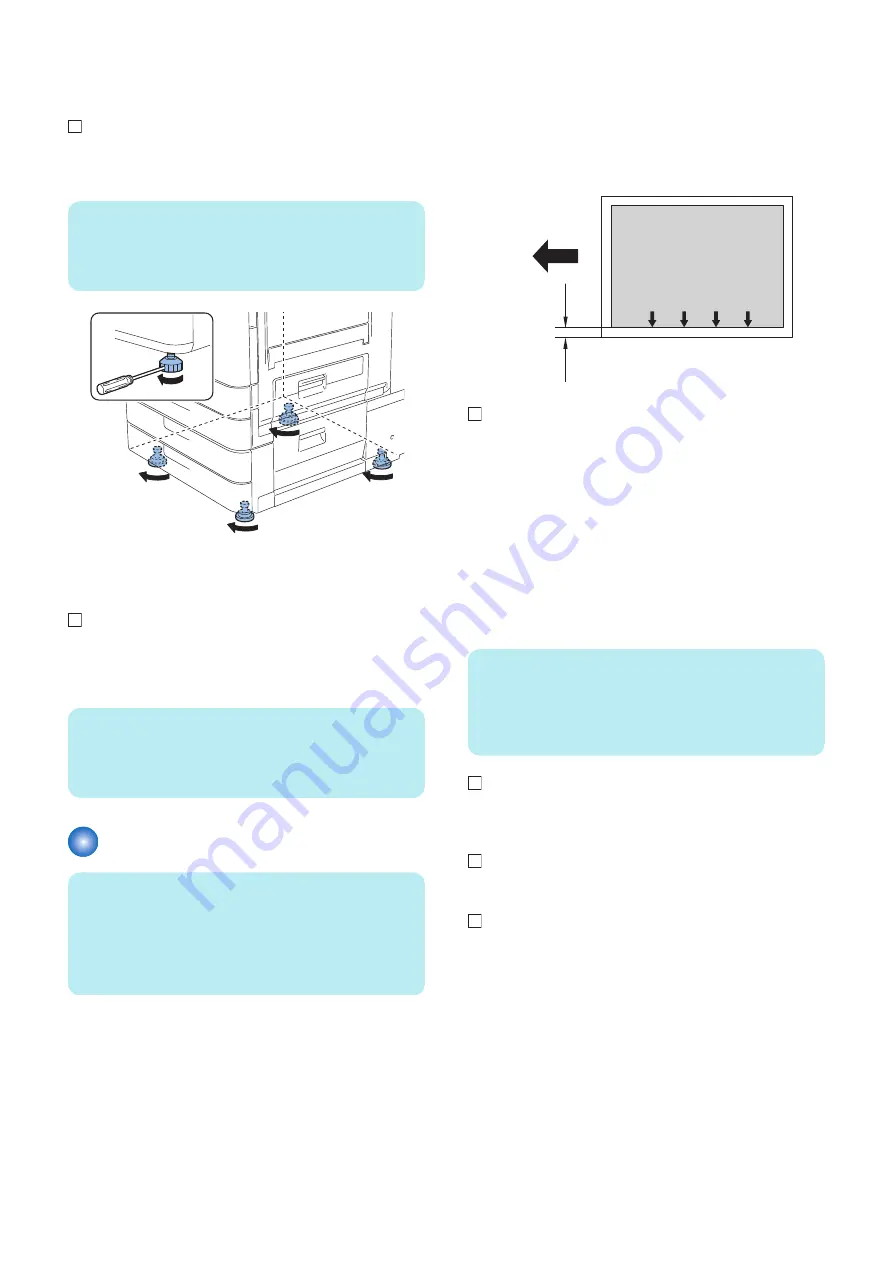
■ Securing the Host Machine
1
Move the host machine to the installation position,
and secure it in place by turning the 4 adjusters of the
Cassette Pedestal with screwdrivers.
NOTE:
• Be sure to secure it in place to prevent overturning.
• Securing the adjusters is not a countermeasure for
the earthquake.
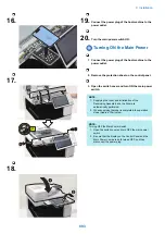
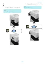
■ Checking the Print Image
1. Place a document on the document glass, copy it by
feeding paper from the cassette or manual-feed tray,
and then check the quality of the print image.
NOTE:
• Abnormal noise is not occurred.
• The specified number of sheets of paper is copied
normally.
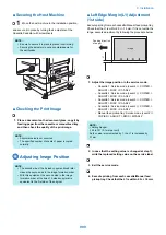
Adjusting Image Position
NOTE:
• The second side of the 2-sided copy mentioned later
means the second side in the image formation order.
• With this equipment, the second side in the image
formation order at the time of 2-sided copy/print is
equivalent to the first side of the original.
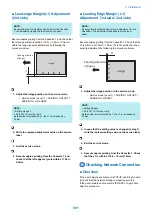
■ Left Edge Margin(L1) Adjustment
(1st side)
Execute printing from each cassette/Manual feed pickup tray.
Check that the L1 is within 2.5 +/- 1.5mm. If it is not within the
range, execute adjustment by following the procedure below.
L
1
Feeding direction
of paper
image
1. Adjust the image position in the service mode.
• Cassette 1: Service mode (Level 2) > COPIER >
ADJUST > MISC > C1-ADJ-Y
• Cassette 2: Service mode (Level 2) > COPIER >
ADJUST > MISC > C2-ADJ-Y
• Cassette 3: Service mode (Level 2) > COPIER >
ADJUST > MISC > C3-ADJ-Y
• Cassette 4: Service mode (Level 2) > COPIER >
ADJUST > MISC > C4-ADJ-Y
• Manual feed pickup tray: Service mode (Level 2) >
COPIER > ADJUST > MISC > MFADJ-Y
NOTE:
< Setting Range>
-128 to 127 (0.1mm per unit)
As the value is incremented by 1, the L1 is increased by
0.1mm.
2. In case that the setting value is changed at step 1),
write the replaced setting value on the service label.
3. Exit the service mode.
4. Execute printing from each cassette/Manual feed
pickup tray. Check that the L1 is within 2.5 +/- 1.5mm.
9. Installation
900
Summary of Contents for imagerunner advance 4551i
Page 19: ...Product Overview 1 Product Lineup 7 Features 13 Specifications 16 Name of Parts 26 ...
Page 155: ...Periodical Service 3 Consumable Parts List 143 Cleaning Check Adjustment Locations 146 ...
Page 392: ...Error Jam Alarm 7 Overview 380 Error Code 383 Jam Code 509 Alarm Code 520 ...
Page 545: ...Service Mode 8 Overview 533 COPIER 549 FEEDER 845 SORTER 851 BOARD 871 ...
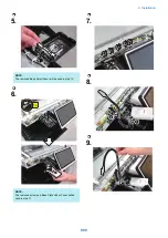
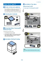
Page 892: ...Unpacking 1 2 1200 mm 840 mm 769 mm 1230 mm 2430 mm 3 9 Installation 879 ...
Page 895: ...3 4 NOTE Keep the removed screws for relocating the host machine 2x 5 6 7 9 Installation 882 ...
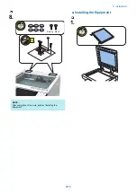
Page 896: ...8 9 10 1x Installing the Air Filter 1 9 Installation 883 ...
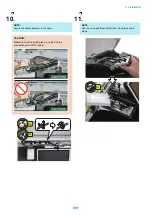
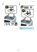
Page 897: ...2 3 Installing the Drum Unit 1 2 3 9 Installation 884 ...
Page 899: ...8 NOTE The screw removed at procedure 4 is used 1x 9 10 11 12 9 Installation 886 ...
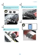
Page 923: ...5 6 NOTE Use the screws and Rubber Caps removed in step 1 2x 7 2x 9 Installation 910 ...
Page 935: ...7 1x 8 9 6x 10 2x 9 Installation 922 ...
Page 936: ...11 Installing the NFC Kit 1 2 2x 3 TP M3x4 1x 9 Installation 923 ...
Page 938: ...4 5 1x 6 9 Installation 925 ...
Page 985: ...8 2x 2x TP M4x8 Black When installing the USB Keyboard 1 9 Installation 972 ...
Page 991: ...7 4x 8 1x 1x Lower Cover 9 1x 10 1x 1x 9 Installation 978 ...
Page 992: ...11 1x 1x 12 1x 13 TP M3x12 2x 14 4x TP M3x6 9 Installation 979 ...
Page 997: ...Installation Procedure 1 2 2x 3 2x 4 6x 5 4x 9 Installation 984 ...
Page 998: ...6 7 NOTE Do not close the Wire Saddle 1x 1x 8 9 9 Installation 985 ...
Page 1003: ...2 1x 1x 3 2x 2x 4 9 Installation 990 ...
Page 1012: ...2 1x 1x 3 2x 2x 4 9 Installation 999 ...
Page 1014: ...7 CAUTION The connector must be contacted TP㸹M3x6 3x 1x 8 4x 9 9 Installation 1001 ...
Page 1016: ...13 4x 14 15 Binding M4x16 Binding M3x16 2x M3x16 M4x16 16 Binding M4x6 1x 9 Installation 1003 ...
Page 1023: ...Installation Procedure Preparation 1 4x 2 1x 1x 3 2x 9 Installation 1010 ...
Page 1029: ...4 5 1x 1x 9 Installation 1016 ...
Page 1048: ...3 2x TP M3x8 Black 4 2x TP M3x6 5 9 Installation 1035 ...
Page 1053: ... Installing the Removable HDD Kit 1 2x 2x 2 3 1x 4 9 Installation 1040 ...
Page 1065: ...3 2x TP M3x8 Black 4 2x TP M3x6 5 9 Installation 1052 ...
Page 1071: ... Installing the Removable HDD Kit 1 2x 2x 2 3 1x 4 9 Installation 1058 ...


