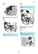


■ Checking Network Connection
CAUTION:
Use the network cable of rank 5e or higher. In addition,
use of shield type (STP cable) is recommended.
When non-shield type (UTP cable) is used, the
surrounding electronic equipments may be interfered
via the network cable.
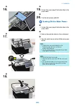
1. Turn OFF the main power switch.
2. Connect the network cable to the host machine and
turn ON the main power switch.
3. Inform the system administrator at the installation
site that the installation of the host machine is
complete, and ask for network connection of the
host machine.
NOTE:
Network setting cannot be executed unless logging in as
an administrator.
Factory default password is as follows.
• System administration division ID: Administrator
• System administration password: 7654321
CAUTION:
Following setting needs to be ON to perform network
setting:
• [Settings/Registration] > [Preferences] >
[Network] > [Confirm Network Connection Set.
Changes]
• [Settings/Registration] > [Preferences] >
[Network] > [TCP/IP Settings] > [IPv4 Settings] >
[Use IPv4]
4. Turn OFF the main power switch.
5. Turn ON the main power switch.
■ Ping Operation Procedure
1. Select [Settings/Registration] > [Preferences] >
[Network] > [TCP/IP Settings] > [IPv4 Settings] >
[PING Command].
2. Enter IP address with numeric keypad on the control
panel and press "Start" key. "Response from the
host" is displayed if Ping operation is successful.
"No response from the host" is displayed if Ping
operation fails.
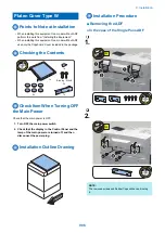
■ Checking with Remote Host
Address
You can check whether the network is connected or not by
using remote host address to execute Ping.
Remote host address: IP address of PC terminal that is
connected to/works with TCP/IP network environment, which
connects to this host machine.
1. Inform the system administrator to execute
checking of network connection using Ping.
2. Check the remote host address with the system
administrator.
3. Enter the remote host address to PING.
• "Response from the host": The machine is properly
connected to the network.
• "No response from the host": Execute the following
troubleshooting because the machine is not
connected to the network.
Troubleshooting of Network
■ Checking Connection of the
Network Cable
Check that the network cable is properly connected to the
Ethernet port.
■ Ping Operation Procedure
1. Ask the network administrator at the user's site to
note the IP address of the PC that is connected to
the network.
2. Select: [Settings/Registration] > [Preferences] >
[Network] > [TCP/IP Settings] > [IPv4 Settings] >
[PING Command], and enter the IP address of PC
with the numeric keypad, and then press "Execute”
key.
• If the display shows "Response from the host", the
network connection is properly functioning.
• If the display shows "No response from the host",
go to the next step for another checking.
NOTE:
Checking of IP address of PC is available by the procedure
below.
On Windows PC, go through the following: Start >
Program > Accessory > Command Prompt, and enter
ipconfig and press the Enter key. IP address information
will be displayed.
■ Checking Network Setting of the
Host Machine
Check if the IP address specified on the host machine is
correct.
1. Select the following: [Settings/Registration] >
[Preferences] > [Network] > [TCP/IP Settings] > [IPv4
Settings] > [IP Address Settings], and note the IP
address in the IP Address field.
2. Select the following: [Settings/Registration] >
[Preferences] > [Network] > [TCP/IP Settings] > [IPv4
9. Installation
902
Summary of Contents for imagerunner advance 4551i
Page 19: ...Product Overview 1 Product Lineup 7 Features 13 Specifications 16 Name of Parts 26 ...
Page 155: ...Periodical Service 3 Consumable Parts List 143 Cleaning Check Adjustment Locations 146 ...
Page 392: ...Error Jam Alarm 7 Overview 380 Error Code 383 Jam Code 509 Alarm Code 520 ...
Page 545: ...Service Mode 8 Overview 533 COPIER 549 FEEDER 845 SORTER 851 BOARD 871 ...
Page 892: ...Unpacking 1 2 1200 mm 840 mm 769 mm 1230 mm 2430 mm 3 9 Installation 879 ...
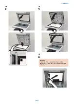
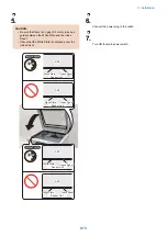
Page 895: ...3 4 NOTE Keep the removed screws for relocating the host machine 2x 5 6 7 9 Installation 882 ...
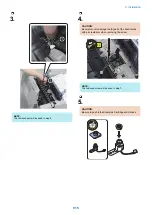
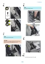
Page 896: ...8 9 10 1x Installing the Air Filter 1 9 Installation 883 ...
Page 897: ...2 3 Installing the Drum Unit 1 2 3 9 Installation 884 ...
Page 899: ...8 NOTE The screw removed at procedure 4 is used 1x 9 10 11 12 9 Installation 886 ...
Page 923: ...5 6 NOTE Use the screws and Rubber Caps removed in step 1 2x 7 2x 9 Installation 910 ...
Page 935: ...7 1x 8 9 6x 10 2x 9 Installation 922 ...
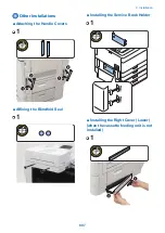
Page 936: ...11 Installing the NFC Kit 1 2 2x 3 TP M3x4 1x 9 Installation 923 ...
Page 938: ...4 5 1x 6 9 Installation 925 ...
Page 985: ...8 2x 2x TP M4x8 Black When installing the USB Keyboard 1 9 Installation 972 ...
Page 991: ...7 4x 8 1x 1x Lower Cover 9 1x 10 1x 1x 9 Installation 978 ...
Page 992: ...11 1x 1x 12 1x 13 TP M3x12 2x 14 4x TP M3x6 9 Installation 979 ...
Page 997: ...Installation Procedure 1 2 2x 3 2x 4 6x 5 4x 9 Installation 984 ...
Page 998: ...6 7 NOTE Do not close the Wire Saddle 1x 1x 8 9 9 Installation 985 ...
Page 1003: ...2 1x 1x 3 2x 2x 4 9 Installation 990 ...
Page 1012: ...2 1x 1x 3 2x 2x 4 9 Installation 999 ...
Page 1014: ...7 CAUTION The connector must be contacted TP㸹M3x6 3x 1x 8 4x 9 9 Installation 1001 ...
Page 1016: ...13 4x 14 15 Binding M4x16 Binding M3x16 2x M3x16 M4x16 16 Binding M4x6 1x 9 Installation 1003 ...
Page 1023: ...Installation Procedure Preparation 1 4x 2 1x 1x 3 2x 9 Installation 1010 ...
Page 1029: ...4 5 1x 1x 9 Installation 1016 ...
Page 1048: ...3 2x TP M3x8 Black 4 2x TP M3x6 5 9 Installation 1035 ...
Page 1053: ... Installing the Removable HDD Kit 1 2x 2x 2 3 1x 4 9 Installation 1040 ...
Page 1065: ...3 2x TP M3x8 Black 4 2x TP M3x6 5 9 Installation 1052 ...
Page 1071: ... Installing the Removable HDD Kit 1 2x 2x 2 3 1x 4 9 Installation 1058 ...


