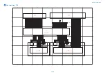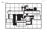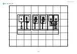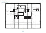
background image

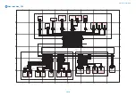
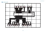
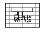
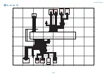
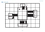
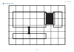
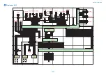
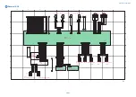
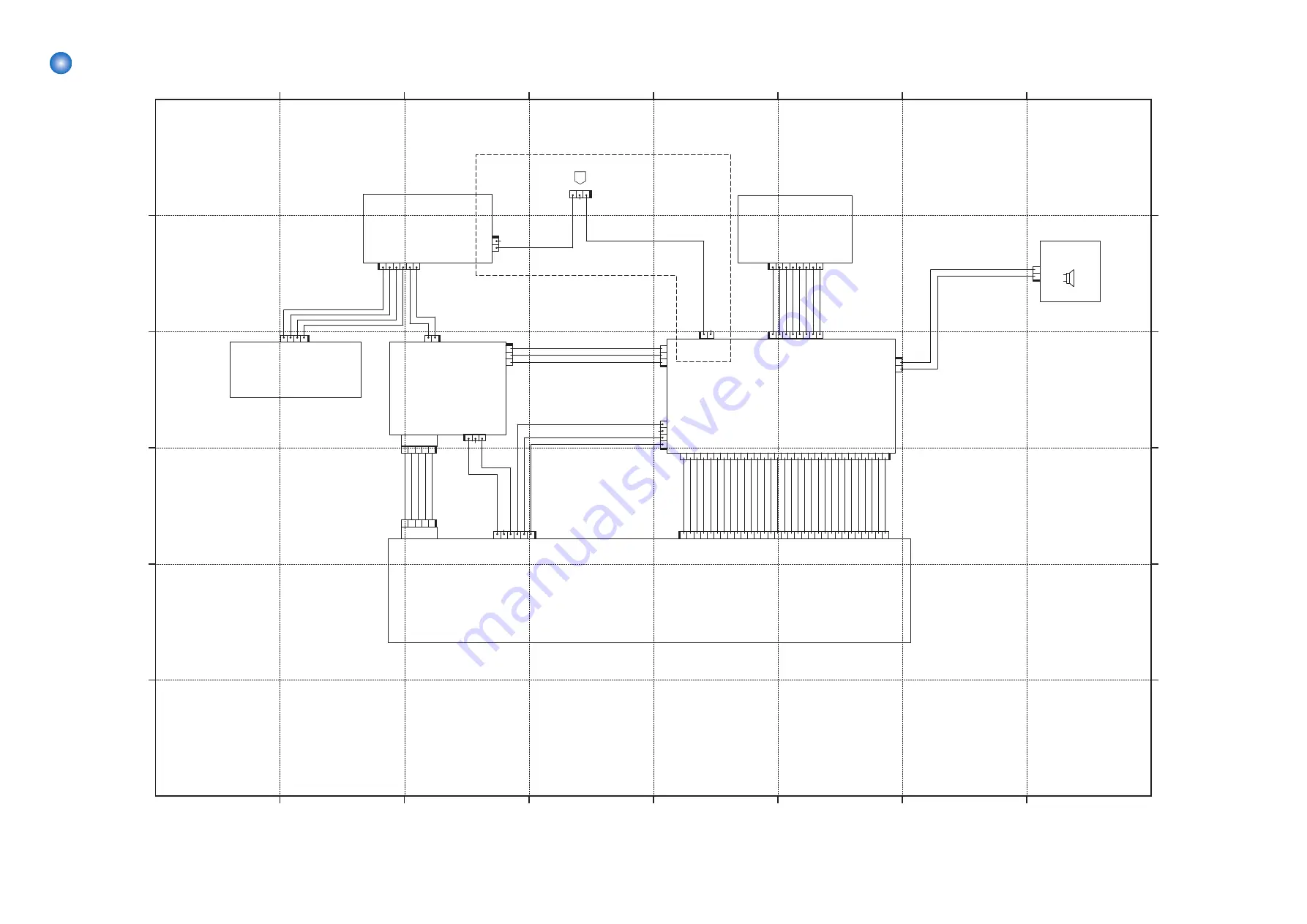
 Host machine_10/18

A

C

B

D

E

F

A

C

B

D

E

F

4

3

2

7

6

5

1

8

4

3

2

7

6

5

1

8

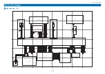
UN18

G3 2nd Line FAX PCB

UN19

Modular PCB (2 to 4 lines)

UN70

G3 3rd/4th Line FAX PCB

3 4 5

1 2

J708

(J4013)

N

.C

.

G

N

D

+12S_U

I_F

AX

G

N

D

+5C

_F

AX

+12S_U

I_F

AX

(J4012)

EXB_

AD

D

R

2

EXB_

D

T

0

EXB_

D

T

1

EXB_

AD

D

R

3

EXB_

D

T

2

EXB_

AD

D

R

4

EXB_

D

T

3

EXB_

AD

D

R

5

G

N

D

EXB_

AD

D

R

1

G

N

D

(J4011)

EXB_

AD

D

R

8

#

R

ESET

_

F

AX

#

EXB_

C

S1

#

EXB_

WE

#

EXB_

O

E

EXB_

D

T

7

#

F

O

F

F

H

K

#

F

C

ID

G

N

D

EXB_

D

T

5

EXB_

AD

D

R

6

EXB_

D

T

4

EXB_

AD

D

R

7

EXB_

D

T

6

G

N

D

#

IN

T

_

F

AX

+3

.3

R

#

F

C

ID

_

U

SB

#

MO

D

EM_

SN

S

G

N

D

3 4 5

1 2

G

N

D

SET_R

ST_F

AX_N

+3.3R

_F

AX

U

SBF

AX_D

N

U

SBF

AX_D

P

N.

C.

(J2)

(J1)

(J403)

(MiniUSB)

(J5)

N.C.

(J2)

2

_

L

IN

E_

L

2

2

_

L

IN

E_

L

1

3

_

L

IN

E_

L

1

3

_

L

IN

E_

L

2

4

_

L

IN

E_

L

1

4

_

L

IN

E_

L

2

(J2)

(J8)

(J6)

MONI_USB

GND

#FC_USB_IN

N.

C.

(J7)

(J3)

(J4)

(J4)

N.C

(J1)

T2

T1

N.

C

N.

C

L1

CT2

CT1

L2

GND

SP_OUT

(J2)

BL

BL

3

4

5

6

1

2

J704

1 2 3 4 5 6 7 8 9 10111213141516171819202122232425262728293031

J701

1

2

3

4

5

6

7

8

9

10

11

12

13

14

15

16

17

18

19

20

21

22

23

24

25

26

27

28

29

30

31

2

3

4

1

2 3

1

J742

J24

J1

7

2

3

4

1

J26

2 1

J30

1

2

3

J35

J36

1

2

3

2

1

J772

8

1 2 3 4 5 6 7

J733

1

2

J3

1

4

0

D

3 4 5 6

1 2

J775

2

1

8

1 2 3 4 5 6 7

J771

1

2

J751

2

1

J773

2

3

1

J804F

From P.1

E-4

Only for JP

UN14

Riser PCB

UN15

G3 FAX PCB

UN20

Modular PCB (1 line)

SP1

FAX Speaker

General Circuit Diagram

1081

Summary of Contents for imagerunner advance 4551i

Page 1: ...SERVICE MANUAL COPYRIGHT 2016 CANON INC CANON imageRUNNER ADVANCE 4500 Series Rev 1 PRINTED IN U S A September 1 2016 Rev 1 imageRUNNER ADVANCE 4551i 4545i 4535i 4525i ...

Page 2: ...g or short period Canon will issue a new edition of this manual The following paragraph does not apply to any countries where such provisions are inconsistent with local law Trademarks The product names and company names used in this manual are the registered trademarks of the individual companies Copyright This manual is copyrighted with all rights reserved Under the copyright laws this manual ma...

Page 3: ... door and closing the delivery unit door which results in supplying the machine with power 2 In the digital circuits 1 is used to indicate that the voltage level of a given signal is High while 0 is used to indicate Low The voltage value however differs from circuit to circuit In addition the asterisk as in DRMD indicates that the DRMD signal goes on when 0 In practically all cases the internal me...

Page 4: ...machine 7 Pickup Delivery System Options 8 Scanning System Options 9 Function Expansion System Options 10 Features 13 Product Features 13 Toner Container 14 Setup Guide 14 Introduction of Situation Mode 15 Specifications 16 Product Specifications 16 Weight and Size 17 Productivity Print speed 17 Paper type 17 Name of Parts 26 External View 26 Cross Section View 30 Control Panel 32 2 Technology 33 ...

Page 5: ...perature control 106 Print temperature control 107 Down sequence control 109 Fixing pressure roller cleaning sequence 111 Fixing film edge cooling control 111 Paper loop amount control before fixing 111 Fixing pressure pressure release control 112 Protection features 113 Pickup Feed System 114 Overview 114 Cassette Pickup Assembly 119 Multi Purpose Pickup Assembly 123 Fixing Registration Assembly ...

Page 6: ... 178 Removing the Left Cover 179 Removing the Left Rear Cover 180 Removing the Right Front Upper Cover 180 Removing the Right Rear Cover Upper 181 Removing the Right Rear Cover Lower 182 Removing the Rear Cover 183 Removing the Rear Lower Cover 184 Removing the Delivery Tray 1 185 Removing the Delivery Tray 2 186 Removing the Delivery Rear Cover Upper Lower 187 Original Exposure System 188 Removin...

Page 7: ...tion Pad 283 Removing the Cassette Pickup Roller 1 2 284 Removing the Cassette Feed Roller 1 2 285 Removing the Cassette Separation Roller 1 2 286 Removing the Main Drive Unit 286 Removing the Second Delivery Unit 290 Removing the First Delivery Unit 291 Removing the First Delivery Drive Assembly 292 External Auxiliary Control System 293 Removing the DC Controller PCB 293 Removing the HVT PCB 293 ...

Page 8: ...oad mode Method 1 361 Saving to a USB Device with Counter Key Numeric Key Methods 2 and 4 363 Saving to a PC Using SST Method 3 364 Saving to a USB Flash Drive Using Service Mode Method 5 367 Service Mode Relating to Debug Logs 367 Collecting the Log of Key Operations 370 Network Packet Capture 371 7 Error Jam Alarm 379 Overview 380 Location Code 380 Pickup Position Code 380 Pickup size 381 Points...

Page 9: ...ce Print Data 541 SITUATION Mode 546 Function to Mask the Screen during Remote Access 546 COPIER 549 DISPLAY 549 I O 622 ADJUST 640 FUNCTION 689 OPTION 716 TEST 817 COUNTER 823 FEEDER 845 DISPLAY 845 ADJUST 845 FUNCTION 847 OPTION 850 SORTER 851 ADJUST 851 FUNCTION 864 OPTION 866 BOARD 871 OPTION 871 9 Installation 872 How to Read the Symbols 874 Symbols 874 Points to Note before Installation 875 ...

Page 10: ...dure 906 Stamp Unit B1 914 Checking the Contents 914 Check Item When Turning OFF the Main Power 914 Installation Outline Drawing 914 Installation Procedure 914 Operation Check 919 NFC Kit C1 920 Points to Note at Installation 920 Checking the Contents 920 Check Item When Turning OFF the Main Power 920 Installation Outline Drawing 920 Remove the Control Panel 920 Installing the NFC Kit 923 Installi...

Page 11: ...nner 2Way Tray L1 973 Checking Before Installation 973 Checking the Contents 973 Installation Procedure 973 Checking after Installation 974 Copy Card Reader F1 975 Checking before Installation 975 Check Item When Turning OFF the Main Power 975 Installation Outline Drawing 975 Checking the Contents 975 Installation Procedure 976 Checking after Installation 981 IC Card Reader Box C1 983 Points to No...

Page 12: ...HDD Preparation 1015 TYPE 1 Option HDD 1TB 1017 Checking the Contents 1017 Check Item When Turning OFF the Main Power 1017 Installation Procedure 1017 TYPE 2 Removable HDD Kit 1020 Checking the Contents 1020 Check Item When Turning OFF the Main Power 1020 Installation Procedure 1020 TYPE 3 Option HDD 1TB Removable HDD Kit 1026 Checking the Contents 1026 Check Item When Turning OFF the Main Power 1...

Page 13: ...e_6 18 1077 Host machine_7 18 1078 Host machine_8 18 1079 Host machine_9 18 1080 Host machine_10 18 1081 Host machine_11 18 1082 Host machine_12 18 1083 Host machine_13 18 1084 Host machine_14 18 1085 Host machine_15 18 1086 Host machine_16 18 1087 Host machine_17 18 1088 Host machine_18 18 1089 Single pass ADF 1090 Reversal ADF 1091 Software Counter Specifications 1092 Removal 1096 Overview 1096 ...

Page 14: ...er Safety 2 Handling of Laser System 2 Turn power switch ON 2 Power Supply 3 Toner Safety 3 Notes When Handling a Lithium Battery 3 Notes Before it Works Serving 4 Points to Note at Cleaning 4 Notes on Assembly Disassembly 4 ...

Page 15: ...into an eye during the work The following warnings are given to comply with Safety Principles EN60950 1 Diese Maschine ist der Klasse 1 der Laserprodukte zugeordnet Innerhalb der Maschine wird jedoch ein Laserstrahl der Klasse 3B ausgestrahlt und es ist gefährlich wenn dieser Strahl in die Augen gerät Bei Servicearbeiten am oder in der Nähe des Laserteils zuerst das Hauptgerät abschalten Bei Servi...

Page 16: ...o an extension cord It may cause a fire or electrical shock The socket outlet shall be installed near the equipment and shall be easily accessible Toner Safety About Toner Toner is a nontoxic matter composed of plastic iron and a trace of pigments CAUTION Never throw toner in flames to avoid explosion Handling Adhered Toner Use dry tissue paper to wipe off toner adhered to skin or clothes and wash...

Page 17: ...ng area will absorb moisture and cause an insulation failure Points to Note at Cleaning When performing cleaning using organic solvent such as alcohol be sure to check that the component of solvent is vaporized completely before assembling Notes on Assembly Disassembly Follow the items below to assemble disassemble the device 1 Disconnect the power plug to avoid any potential dangers during assemb...

Page 18: ...triangle mark take care not to apply too much force when tightening the screw The recommended torque value is shown below as a reference value Type of Screws RS tight W Sams Binding TP Fastened member Metal Resin Metal Resin Metal Resin Metal Resin Tightening torque N m M4 Approx 1 6 Approx 1 6 Approx 1 6 Approx 0 8 Approx 1 6 Approx 0 8 Approx 1 6 Approx 0 8 M3 Approx 0 8 Approx 0 8 Approx 0 6 Ap...

Page 19: ...Product Overview 1 Product Lineup 7 Features 13 Specifications 16 Name of Parts 26 ...

Page 20: ... the print speed ppm print per minute iR ADV 4551 4551i iR ADV 4545 4545i iR ADV 4535 4535i iR ADV 4525 4525i Print speed 51 ppm 45 ppm 35 ppm 25 ppm Positioning Target machine iR ADV 4251 4245 4235 4225 Series Control Panel Flat Control Panel HDD Standard 250 GB Maximum 1 TB ADF Standard 1 Product Overview 7 ...

Page 21: ...e paper in the paper deck Cassette Heater Unit 37 Cassette Heater Unit 41 2 Cassette Feeding Unit AN1 3 High Capacity Cassette Feeding Unit B1 FL Cassette BC1 Option for 2nd cassette of the host machine FL Cassette BD1 Option for 1st cassette of the host machine Envelope Feeder Attachment D1 Option for 2nd cassette of the host machine Delivery System Options No Product name Required options condit...

Page 22: ...Y1 4 Hole Puncher Unit A1 Option for Staple Finisher Y1 or Booklet Finisher Y1 Inner 2 3 Hole Puncher C1 Option for Inner Finisher J1 Inner 2 F4 Hole Puncher C1 Option for Inner Finisher J1 Inner S4 Hole Puncher C1 Option for Inner Finisher J1 Scanning System Options Required Options and Conditions 3 5 6 2 4 1 No Product name Required options conditions etc 1 Platen Cover Type W 2 ADF Access Handl...

Page 23: ...th Copy Control Interface Kit A1 is not available 6 Copy Card Reader Attachment B5 Required when Card Reader F1 is installed 7 Serial Interface Kit K3 Using with Copy Card Reader F1 is not available Using with Copy Control Interface Kit A1 is not available 8 Copy Control Interface Kit A1 Using with Serial Interface Kit K3 is not available Using with Copy Card Reader F1 is not available 9 2 5inch 2...

Page 24: ...required when installing the Paper Deck Heater Unit C1 Drum Heater C1 Power Supply Cable V1 IR ADV SEC KIT S1 2600 HDD Mirroring Kit J1 is required An option required to make this product as an IEEE2600 1 certified model License Products At the time of installation obtain the license number according to the license certificate included Then enter the obtained license number from the Control Panel ...

Page 25: ...Product name Required options conditions etc Card Set A4 Card Set A5 Card Set A6 imageRUNNER ADVANCE 4545i Series License 1 Product Overview 12 ...

Page 26: ...led Security policy supported Forcible printing of user information Equipped with HDD Encryption Board as standard Wi Fi supported 4 Image Formation System High durable drum Increased capacity of toner container Automatic delivery of toner Improved durability of consumable parts 5 Pickup Feed System Large capacity of pedestal supported Single action operation of pulling out of a cassette 6 Improve...

Page 27: ...installation of a device in the format of a navigation The items that can be set are as follows Display order Setting screen Remarks 1 Switch Language Keyboard If canceled the device starts up without Setup Guide 2 Paper Settings Paper Settings 3 Authentication Login If skipped the screen proceeds to Auto Adjust Gradation User Authentica tion is standard 4 Date Time Settings Sets the date and time...

Page 28: ...archability of service technicians at the site This mode makes it possible to easily use the service mode appropriate for the scene at the site Category SITUATION MODE Detail Installation Items related to installation Troubleshooting Items related to troubleshooting Parts Replacement Items performed at parts replacement Major Adjustment Major items of adjustment Sensor Check Operation Check of Ele...

Page 29: ...TBD First copy time 51 ppm machine 3 7 sec or less 45 35 ppm machine 3 8 sec or less 25 ppm machine 5 2 sec or less Paper type Cassette Thin paper 2 60 g m2 to 63 g m2 Plain paper 1 64 g m2 to 75 g m2 Plain paper 2 76 g m2 to 90 g m2 Plain paper 3 91 g m2 to 105 g m2 Heavy paper 1 106 g m2 to 128 g m2 Recycled paper 1 Colored paper 1 Pre punched paper 1 1 Only 1 side Manual feed pickup tray Thin p...

Page 30: ...ass DADF A1 565 556 158 13 5 DADF AV1 565 540 139 8 2 Cassette Feeding Unit AN1 565 650 248 TBD High Capacity Cassette Feeding Unit B1 565 650 248 TBD Paper Deck Unit F1 400 630 440 31 Booklet Finisher Y1 537 623 1095 57 Staple Finisher Y1 537 623 1095 31 Inner Finisher J1 621 8 535 205 7 2 Productivity Print speed Unit sheets min Paper size iR ADV 4551 iR ADV 4545 iR ADV 4535 iR ADV 4525 A4 51 45...

Page 31: ...5R Yes Yes Yes Yes Yes No No 11x17 Yes No Yes Yes Yes No No LGL Yes Yes Yes Yes Yes No No LTR Yes Yes Yes Yes Yes No No LTRR Yes Yes Yes Yes Yes No No STMTR Yes Yes Yes Yes Yes No No EXEC Yes Yes Yes Yes Yes No No OFFICIO Yes Yes Yes Yes Yes No No E OFFICIO Yes Yes Yes Yes Yes No No B OFFICIO Yes Yes Yes Yes Yes No No M OFFICIO Yes Yes Yes Yes Yes No No A OFFICIO Yes Yes Yes Yes Yes No No A LTR Ye...

Page 32: ...Yes Yes Yes Yes No No 11x17 Yes No Yes Yes Yes No No LGL Yes Yes Yes Yes Yes No No LTR Yes Yes Yes Yes Yes Yes Yes LTRR Yes Yes Yes Yes Yes No No STMTR Yes Yes Yes Yes Yes No No EXEC Yes Yes Yes Yes Yes No No OFFICIO Yes Yes Yes Yes Yes No No E OFFICIO Yes Yes Yes Yes Yes No No B OFFICIO Yes Yes Yes Yes Yes No No M OFFICIO Yes Yes Yes Yes Yes No No A OFFICIO Yes Yes Yes Yes Yes No No A LTR Yes Yes...

Page 33: ...o No No No No No LTRR Yes No No No No No No STMTR Yes No No No No No No EXEC Yes No No No No No No OFFICIO Yes No No No No No No E OFFICIO Yes No No No No No No B OFFICIO Yes No No No No No No M OFFICIO Yes No No No No No No A OFFICIO Yes No No No No No No A LTR Yes No No No No No No A LTRR Yes No No No No No No GLTR R Yes No No No No No No GLTR Yes No No No No No No GLGL Yes No No No No No No AFL...

Page 34: ...om size 1 1 Custom size 1 2 Custom size 1 3 Custom size 2 1 Custom size 2 2 Custom size 2 3 Custom size 3 1 Custom size 3 2 Custom size 3 2 Custom size 3 3 Custom size 5 Long length Pickup Specifications 5 11 Type paper weight g m2 Clear film 151 to 181 Paper size Pickup position Multi pur pose Tray Cassette 1 Cassette 2 Cassette 3 Cassette 4 Paper Deck Unit F1 High Capaci ty Cassette Feeding Unit...

Page 35: ...s No No No No No No LGL Yes No No No No No No LTR Yes No No No No No No LTRR Yes No No No No No No STMTR Yes No No No No No No EXEC Yes No No No No No No K8 Yes No No No No No No K16 Yes No No No No No No F4A Yes No No No No No No I LGL Yes No No No No No No Free Yes No No No No No No Custom size A Yes No No No No No No Custom size A Custom size 1 1 Custom size 1 2 Custom size 1 3 Custom size 2 1 ...

Page 36: ...ckup Specifications 9 11 Type paper weight g m2 Postcard 4 on 1 postcard 164 to 209 Paper size Pickup position Multi pur pose Tray Cassette 1 Cassette 2 Cassette 3 Cassette 4 Paper Deck Unit F1 High Capaci ty Cassette Feeding Unit A1 Postcard Yes No No No No No No Reply Postcard Yes No No No No No No 4 on 1 Postcard Yes No No No No No No Pickup Specifications 10 11 Type paper weight g m2 Pre Punch...

Page 37: ...es No No I LGL Yes Yes Yes Yes Yes No No Free Yes No No No No No No Custom size A Yes No No No No No No Custom size B Yes Yes Yes Yes Yes No No Custom size C Yes No Yes Yes Yes No No Custom size A Custom size 1 1 Custom size 1 2 Custom size 1 3 Custom size 2 1 Custom size 3 1 Custom size 5 Long length Custom size B Custom size 2 2 Custom size 3 2 Custom size C Custom size 2 3 Custom size 3 3 Picku...

Page 38: ...No DL No No No No No No No Nagagata 3 No No No No No No No Yougatanaga 3 No No No No No No No Kakugata 2 No No No No No No No Free No No No No No No No Free Long length No No No No No No No Custom size A Yes No No No No No No Custom size A Custom size 1 1 Custom size 1 2 Custom size 1 3 Custom size 2 1 Custom size 2 2 Custom size 2 3 Custom size 3 1 Custom size 3 2 Custom size 3 3 1 Product Overvi...

Page 39: ...me No Name 1 Motion Sensor 8 Multi purpose Tray 2 Control Panel 9 Right Lower Door 3 ADF 10 Cassette Right Door 4 USB Port Right Front 11 Cassette 1 5 USB Port Right Rear 12 Cassette 2 6 USB Connector 13 Main Power Supply Switch 7 LAN Port 1 Product Overview 26 ...

Page 40: ...over 2 Delivery Tray 4 Front Cover Rear side of the machine No Name No Name 1 Extension phone line terminal LINE 4 LINE 3 LINE 2 from above 3 Handset connection terminal Handset 2 Phone line terminal LINE 1 4 External phone terminal EXT 1 Product Overview 27 ...

Page 41: ...er ADF Reader No Name No Name 1 Document Set Lamp 7 Document Read Area Cover 2 ADF Upper Cover 8 Copyboard Glass 3 Slide Guide 9 Document Delivery Extension Tray 4 Document Pickup Tray 10 Document Stopper 5 Document Pickup Extension Tray 11 Document Delivery Tray 1 Product Overview 28 ...

Page 42: ...ed Document Lamp Multi purpose Tray No Name No Name 1 Multi purpose Tray Pickup Side Guide Plate 3 Multi purpose Tray Pickup Sub Tray 2 Multi purpose Tray Cassette No Name No Name 1 Trailing Edge Guide Plate 2 Side Guide Plate 1 Product Overview 29 ...

Page 43: ...D Unit Toner Container Toner Supply Unit Laser Scanner Unit Cassette 2 Cassette 1 Delivery Assembly Fixing Assembly Developing Assembly Drum Unit Drum Reader 2 1 No Name No Name 1 Reader Scanner Unit 2 Reader Unit 1 Product Overview 30 ...

Page 44: ...lout Roller 13 Lead Roller 2 6 Registration Roller 14 Delivery Roller 7 Registration Roller 15 Delivery Roller 8 Lead Roller 1 Reversal ADF 3 4 1 2 6 7 9 8 5 No Name No Name 1 Lower registration roller 6 Lower delivery reversal roller 2 Upper registration roller 7 Read roller 2 upper 3 Pickup roller assembly 8 Platen roller 4 Separation roller 9 Read roller 1 upper 5 Upper delivery reversal roller...

Page 45: ...meric keys 10 Main Power indicator 3 Energy Saver key 11 Error indicator 4 Counter Device Information key 12 Processing Data indicator 5 Brightness Adjustment key 13 Reset key 6 Settings key 14 ID Log In Out key 7 Clear key 15 NFC If equipped with NFC Kit B1 8 Stop key 16 Touch panel display 1 Product Overview 32 ...

Page 46: ...echnology 2 Basic Configuration 34 Original Exposure System 35 Main Controller 78 Laser Exposure System 83 Image Formation System 89 Fixing System 103 Pickup Feed System 114 External Auxiliary System 129 ...

Page 47: ...ation system block fixing system block and pickup feed system block Flow of paper Flow of signal Laser beam Reader controller PCB CCD Exposure lamp Original exposure system Main controller DC controller Option board HDD Controller system Duplexing feed Delivery Transfer Pickup Fixing Fixing system Image formation system Pickup feed system Laser exposure system Cassette 2 Cassette 1 Laser scanner u...

Page 48: ...p roller assembly and the Separation roller Improvement of paper curl detection by the modification the Document length sensor Installation of the Document delivery Lamp function Specifications Reader Assembly Item Specification Function Remarks Photo conductor White high luminance LED light guide plate Scanning of original At copyboard reading Scanning by moving Scanner Unit When Using ADF Stream...

Page 49: ...l Type Sheet document Original basis weight 1 sided A B 38 to 157 g m2 Inch 50 to 157 g m2 2 sided 50 to 157 g m2 Color original 64 to 157 g m2 1 sided A B For originals 38 g m2 or more and less than 42 g m2 width 257 mm B5 size or more and 1 sided single sheet delivery A B For originals exceeding 432 mm 1 sided single sheet feed 60 to 90 g m2 Original size A3 A4 A4R A5 A5R B4 B5 B5R B6R LDR LGL L...

Page 50: ...iginal mode select the following service mode LV 2 and set it to 1 default 0 COPIER OPTION USER MF LG ST Reversal ADF Item Specifications Document pickup method Automatic pickup and delivery Document loading direction Face up Document loading position Aligned to center Document separation method Upper separation Document weight Single sided AB configuration 42 to 128 g m2 Single sided one sheet fe...

Page 51: ...e detection DADF detection at 5 degrees 4 ADF Open Close Sensor 2 PS_N2 ADF open close detection detection of timing for size detection at 30 degrees of ADF opening closing 5 Sensor Lightproof Sheet 6 Reader Controller PCB UN_BO1 Overall Reader control digital image processing 7 Original Size Sensor 1 PS_R1 Size detection in the vertical scanning direction AB configuration 8 Original Size Sensor 2...

Page 52: ...Unit By using the Lens Unit with 4 lenses combined downsizing of the Scanner Unit has been achieved Reading Sensor The Reading Sensor reads the image for1 image line The Reading Sensor has 4 lines R G B and B W At 600 dpi B W reading 1 line B W is used At color reading 3 lines R G and B are used Related Error Code Light intensity error E301 0001 Light intensity is below the reference level at pape...

Page 53: ...p Assembly Original Pickup Tray Original Scanning Assembly Front Side Original Scanning Assembly Rear Side Original Path Original Delivery Tray ADF Driver PCB Reader Controller PCB Parts Configuration 1 2 3 4 5 6 7 8 Key No Name Code 1 ADF Stamp Solenoid SL1 2 Scanner Unit 3 ADF Pickup Clutch CL1 4 ADF Registration Motor STM1 2 Technology 40 ...

Page 54: ...g unit Scanner Unit for the back side of originals The drive configuration of this equipment is indicated below M2 M1 CL1 M3 SL1 Code Name Role STM1 ADF Registration Motor Drive of Pickup Roller STM2 ADF Pickup Motor Drive of Registration Roller paper feed STM3 ADF Read Motor Lead Roller Delivery Roller drive Glass shift CL1 ADF Pickup Clutch ON OFF of Pickup Roller Unit lifting operation SL1 ADF ...

Page 55: ... Inch Sensor Identifying A4R LTRR and A5R STMTR paper PS_A5 Cover Open Closed Sensor Opening closing of the Feeder Cover Yes PS_A6 Lead Sensor 1 Lead Roller 1 disengagement timing Yes Yes PS_A7 Lead Sensor 2 Lead Roller 2 disengagement timing Yes Yes PS_A9 Paper Back Reading Glass HP Sensor Reading Glass position UN_BO6 Original Size Sensor Original size in the width direction UN_BO7 Double Feed S...

Page 56: ...A9 Paper Back Reading Glass HP Sensor J405 STM3 ADF Read Motor PS_R2 Registration Sensor J407 CL1 ADF Pickup Clutch UN_BO6 Original Size Sensor SL1 ADF Stamp Solenoid UN_BO7 Double Feed Sensor PCB trans mission PS_A1 Arch Sensor UN_BO8 Double Feed Sensor PCB recep tion PS_A2 Delivery Tray Sensor J410 UN_SNS1 Original Width Volume PS_N1 Original Sensor PS_A3 LTR R LGL Sensor PS_R1 Post separation S...

Page 57: ...lenoid PCB4 Document width sensor PCB M1 Pickup motor PCB5 Document delivery LED PCB M2 Read motor Roller Layout 3 5 4 1 2 6 7 8 9 13 12 10 11 No Name No Name 1 Lower registration roller 8 Read roller 2 lower 2 Upper registration roller 9 Read roller 2 upper 3 Feed roller 10 Platen roller 4 Separation roller 11 Read roller 5 Pickup roller 12 Read roller 1 lower 6 Upper delivery reversal roller 13 ...

Page 58: ... Document length sensor 1 Document size detection length SR8 Document length sensor 2 SR9 Different width sensor 1 Document size detection width SR10 Different width sensor 2 SR11 Different width sensor 3 SR12 Different width sensor 4 SR13 Document width sensor 1 SR14 Document width sensor 2 SR15 Document width sensor 3 Drive Configuration CL1 M1 SL1 M2 CL2 SL2 Symbol Name Role M1 Pickup motor Pic...

Page 59: ...ermines the size of an original by the combination of the measurement results of the reflected light at particular points of the Reflection Sensor and Reading Sensor Furthermore two points are measured for each size to perform accurate detection even if the original is moved when the ADF is closed Horizontal scanning direction Reading Sensor AB configuration 12 point measurement inch configuration...

Page 60: ... the presence absence of dust on the Stream Reading Glass or the Guide Plate of the ADF on the Platen Roller in case of the reverse model or image correction is performed to prevent the dust to be printed on an image This control is performed only when the ADF is being used and has been closed Control timing At job completion At paper interval after each sheet is read At the start of a job only wh...

Page 61: ...arts C B A At paper interval The Scanner Unit does not move Reading is performed at the position determined by the control performed at job completion or at the start of a job and image correction is performed if dust is detected at that position Scanning Glass C B A 0 5 mm 0 5 mm Service mode COPIER OPTION IMG RDR DFDST L1 Adjustment of dust detection level at paper interval COPIER OPTION IMG RDR...

Page 62: ...ection data Digital image signal Reader Controller PCB Main Controller PCB Scanner Unit PCB Reader SRAM CPU ASIC Shading correction Color offset correction in sub scanning LED 4lines Analog image signal Analog image process gain correction offset correction A D conversion CCD AP PCB Scanner Unit PCB ADF EEP ROM Scanner unit drive control Scanner unit drive control Scanner Unit Drive The Reading Se...

Page 63: ...t intensity in the center of the LED and the surrounding area 5 LED deterioration To correct unevenness of the Reading Sensor output shading correction is performed In shading correction there is a type of shading correction that is executed per job Shading correction Shading correction is performed for each scanning of original With this operation light of LED Lamp is emitted to the Standard Whit...

Page 64: ...tionship between the various electrical components is indicated below ADF Driver PCB Scanner Unit Sensor Motor Fan Solenoid Reader Controller PCB Related Error Code Communication error between the Reader Controller PCB and the Scanner Unit E280 0001 Communication between the Reader Controller PCB and the Reader Scanner Unit was not completed within the specified period of time E280 0002 Disconnect...

Page 65: ...inting 1 sided original mix of different configurations 1 sided printing 1 sided original mix of different configurations 2 sided printing Long original 1 sided printing Simultaneous du plex reading Picks up originals reads their front side with the Scanner Unit at the Reader side and reads their back side with the Scanner Unit on the ADF side Then outputs them 2 sided original 1 sided printing 2 ...

Page 66: ... sheet pickup 2 1st sheet arch creation 1 Pullout Roller 3 1st sheet arch creation 1 Registration Roller 4 1st sheet scanning 6 2nd sheet scanning 5 1st sheet delivery 2nd sheet pickup and arch creation 1 Pullout Roller 2 Technology 53 ...

Page 67: ...Scanner Unit ADF Scanner Unit Reader Scanning position for the front side Scanning position for the rear side Service mode FEEDER ADJUST ADJMSCN1 Zoom fine adjustment when reading 2 sided originals horizontal scanning direction front side FEEDER ADJUST ADJMSCN2 Zoom fine adjustment when reading 2 sided originals horizontal scanning direction back side FEEDER ADJUST ADJSSCN1 Zoom fine adjustment wh...

Page 68: ...e Size Small Size Sensor PS_R3 Yes Width AB Inch Sensor PS_A4 Yes Yes Yes Yes Original Width Volume UN_SNS1 Yes Yes Yes Yes During feed Feed Post separation Sensor PS_R1 Yes Yes Yes Yes Lead Sensor 1 PS_A6 Yes Yes Yes Yes Width Original Size Sensor UN_BO6 Yes NOTE Normal mix of same configuration mix of different configurations The measurement value is replaced with a fixed size Long Original mode...

Page 69: ...of the Original Width Volume UN_SNS1 changes according to the Slide Guide The ADF Driver PCB receives this change in the resistance value as an original size signal UN_SNS1 and uses it as the size in the width direction The AB Inch Sensor PS_A4 is located inside the Document Pickup Tray to enable accurate width detection of A4R LTRR and A5R STMTR using the Original Width Volume UN_SNS1 The AB Inch...

Page 70: ...es with the Lightproof Plate and the Lightproof Plate passes through the Photo Interrupter This makes the Original Sensor PS_N1 emit an original detection signal EMP_S If the Cover Open Closed Sensor PS_A5 detects that the Feeder Cover has been closed a Feeder Cover open close detection signal COVER_S is emitted When the ADF Driver PCB receives a Feeder Cover open close detection signal COVER_S an...

Page 71: ...ter completion of the pickup operation the Pickup Roller Unit is lifted up Errors in the pickup operation are detected by the Post separation Sensor PS_R1 If the original could not be detected at the specified timing it is notified as a jam ADF Driver PCB M1 CL1 PS_R1 SEPA_S SEPA_M_A B MV_CL Original Feed Control This equipment forms an arch in the Pullout Roller and Registration Roller locations ...

Page 72: ...tored in the ROM of the Reader Controller PCB which determines the occurrence of a jam by the presence of an original in the areas of corresponding sensors When a jam occurs the machine stores the information by the code This machine s jam code can be checked by printing out a jam error history report from service mode PS_A6 PS_A7 PS_R2 UN_BO8 UN_BO7 PS_R1 PS_A1 2 Technology 59 ...

Page 73: ...ultrasonic method to perform double feed detection Once it is judged that a double feed has occurred the machine stops operation due to a jam When a job is started the sensor level is checked without an original to calculate the threshold value for double feed detection During the job the Post separation Sensor PS_R1 detects and manages the leading edge trailing edge for each original sheet and de...

Page 74: ...riginal 2nd sheet Original 1st sheet Vibration large Vibration large Vibration small Double Feed Detection Jam Loca tion Jam code Types of jam Sensor name Sensor number 01 0020 Double feed jam during a job ADF Double Feed Sensor UN_BO7 UN_BO8 0021 Sensor communication error during a job 0060 Double feed jam during a job first sheet 0061 Sensor communication error during a job first sheet 0062 Sens...

Page 75: ...ctions mode occurs If an error occurs for some reasons a jam message is displayed to make the user to perform jam removal After that an error is displayed and the device enters limited functions mode The machine recovers when the cause of the error is solved If this jam occurs refer to the error log and perform the remedy for the error code which has occurred at the same time NOTE Settings Registr...

Page 76: ...r PCB Solenoid Motor Fan 5V Sensor 24V DADF driver PCB Scanner Unit PCB LED lamp unit Original width volume 24V 5V Related Error Code Power supply 24 V error E227 0101 24 V port is OFF when the power of the DF Unit is turned ON ADF_Reversal ADF Basic Operation Outline The ADF has the following operation modes Operation mode name Outline of operation Associated print mode Forward pickup Delivery Pi...

Page 77: ...en two document sheets are placed Document Pickup of first document sheet Formation of loop Start for reading of the first document sheet Reading of first document sheet Pickup of second document sheet Formation of loop of second document To next 2 Technology 64 ...

Page 78: ...ocument sheet Completion of delivery of first document sheet Completion of delivery of the second document sheet End of job Start of reading of second document sheet Forward Pickup Reverse Delivery Operation Duplex read operation when two document sheets are placed 2 Technology 65 ...

Page 79: ...sheet Position to start of reading of first document sheet Start of reading of front side of first document sheet End of reading of first document sheet Stop after feeing the first document sheet to reversal position To next Document 2 Technology 66 ...

Page 80: ...first document sheet Stop after feeding the first document sheet to reversal position Idle feed of first document sheet Removal of idle registration loop at the first document sheet Re pickup Release of the Lower delivery reversal roller To next Completion of reading of reverse side at the first document sheet Pressurization of the Lower delivery reversal roller 2 Technology 67 ...

Page 81: ...of second document sheet End of reading of front side of second document sheet Stop after feeding the second document sheet to reversal position Delivery of first document sheet Removal of registration loop of reverse side at the second document sheet Re pickup Release of the Lower delivery reversal roller To next 2 Technology 68 ...

Page 82: ...ced on the Document supply tray a document is picked up in the following procedure Pickup operation The Pickup motor M1 drives to lower the Pickup roller assembly through the Pickup clutch CL1 and then the Pickup roller rotates to feed a document The stopper rises in conjunction with the Pickup roller assembly The Separation roller is used to improve the separation performance while feeding a docu...

Page 83: ...nt glass reads the image A document is fed by the Read roller 1 upper and the Platen roller driven by the Read motor M2 The read image is stored in the memory of the host machine Document glass Scanner Platen roller M2 Pickup Roller Assembly and Separation Roller The Pickup roller assembly consists of the Pickup roller and the Feed roller When the start key is pressed or a document pickup signal i...

Page 84: ...cument to the reverse point Upper delivery reversal roller Platen roller Read roller 2 Upper Read roller 1 Upper M2 M2 Reversal Feed 1 After the trailing edge of a fed document passes the Delivery reversal sensor SR3 the Read motor M2 stops Thus a document stops at the reverse point The Read motor M2 drives in reverse direction to feed a document to the Registration roller and then it stops After ...

Page 85: ...y tray Document length sensor 1 2 SR7 SR8 Width Detects the document width on the Document sup ply tray Document width sensor1 2 3 SR13 SR14 SR15 Mixed size print mode and banner paper mode Function Description Symbol Document presence absence detection Detects document existence on the Document sup ply tray Document set sensor SR5 Mixed width document size de tection Length Document length is det...

Page 86: ...e Width mm Document width sensor 1 SR13 Document width sensor 2 Document SR14 Document width sensor 3 SR15 Document length sensor 1 SR7 Document length sen sor 2 SR8 AB INCH AB INCH AB K 143 9 or less OFF OFF OFF ON ON STMTR A5R OFF ON STMTR A5R ON OFF STMTR A5R OFF OFF STMTR STMTR A5R More than 143 9 and 165 0 or less OFF ON ON ON ON A5R A5R OFF ON A5R A5R ON OFF A5R A5R OFF OFF A5R A5R A5R More ...

Page 87: ...width and length are performed The maximum width is detected by the Document width sensor 1 2 3 SR13 SR14 SR15 in the same way of initial document size detection Width other than maximum width is detected by the Different width sensor 1 2 3 4 SR9 SR10 SR11 SR12 Document length is detected by ON state on the Read sensor SR2 and OFF state on the Registration sensor SR1 Each document size is determin...

Page 88: ...h mm 215 9 139 7 11 17 279 0 A B B LTR A B A C LGL 215 9 C LTRR C STMT C Item Contents A Combination assured B Not assured Possible to feed C Not assured Possible to have original jam Out of Specifications Detecting Jams This machine detects document jams using the sensors shown below Document jam check timing is controlled by the host machine which determines jam occurrence by document existence ...

Page 89: ...sor SR1 SR5 01 0096 Limited function 2 01 00A1 Power on Registration sensor SR1 01 00A2 Power on Read sensor SR2 01 00A3 Power on Delivery reversal sensor SR3 1 The sensor of the Reader of the host machine 2 Limited functions jam is a jam for preventing an original to be left inside the machine when a problem which requires the machine moves to limited functions mode occurs If an error occurs for ...

Page 90: ... Indicator After completion of reading the LED at the Document delivery LED PCB PCB5 lights ON to prevent from leaving a document The LED keeps lighting for 10 seconds and then turns OFF PCB5 Related service mode ON OFF of DADF delivery LED Lv 1 COPIER OPTION CUSTOM DFEJCLED 2 Technology 77 ...

Page 91: ...Temporarily storage of image data Capacity of 2 GB for controller control 1 GB for image pro cessing USB port USB2 0 Device I F USB3 0 Host I F Hard disk 2 5 inch SATA I F Standard 250 GB 250 GB usable area address list security information pass word certificate image data preferences Flash PCB Storage of system software 2 GB TPM PCB Generation and storage of the encryption key Only when Managemen...

Page 92: ...J1 TPM PCB J21 Copy Control Interface Kit I F J3 USB I F Device J6000 J5 USB I F Host J6001 Image Data Analyzer PCB J7 LAN I F J6003 J6004 Standard hard disk J9 J11 Flash PCB J6005 Counter Memory PCB J13 Voice Operation Voice Guidance J7000 Riser PCB J15 Controller Fan J8000 J8001 Hard disk for mirroring J18 J20 Serial Interface Kit Copy Card Reader J8002 2 Technology 79 ...

Page 93: ...tions J4000 Main Controller PCB J4023 IC Card Reader upper port USB flash drive for users lower port J4002 AC Driver PCB J4031 Reader Controller PCB J4003 SOFT ID PCB J4201 Main Switch J4011 4012 Fax 1 Line J4202 WIFI PCB J7201 Laser Driver PCB J4013 Fax 2nd 3rd 4th Line J4021 J4022 Control Panel I F J7202 DC Controller PCB J9001 AC Driver PCB 2 Technology 80 ...

Page 94: ...h PCB E614 4001 Error in file system on the Flash PCB E614 4002 Error in file system on the Flash PCB E748 2010 Flash PCB error HDD error NOTE When the following errors occur the system of the host machine has not been started normally Therefore the error code is not recorded in the log E602 XX01 E614 XX01 E748 2010 Shutdown Sequence Before shutting down the power supply it is necessary to perform...

Page 95: ...sensor judges whether he she is just a passer to prevent recovery by mistake CAUTION Recovery time depends on the time for recovery from sleep mode of the host machine The Motion Sensor outputs the trigger for recovery from sleep mode Operation of the Motion Sensor is the same for recovery from Deep Sleep and from Sleep 1 but time for recovery differs depending on the recovery process of the host ...

Page 96: ...on 1200dpi Motor type Brushless motor Motor revolutions 51 ppm machine approx 27000 rpm 45 35 ppm machine approx 16000 rpm 25 ppm machine approx 32000 rpm Number of Scanner Mirror facets 6 facets 40 mm dia Main Configuration Parts Laser Unit Polygon mirror BD PCB BD mirror Name Function Laser Unit Emits laser Polygon mirror Scans the laser light in the main scanning direction BD mirror Reflects th...

Page 97: ...nters stand by mode FG control If pressing the start key before the control panel key is ON standby time gets shorter after the polygon motor reaches the target Print PRINT When copy start key is ON the machine drives A laser After BD PCB detects A laser the machine performs the APC laser intensity control of each laser Oncethe BD signal reaches the specified cycle the machine is ready to print Im...

Page 98: ...A B laser CNT0 0 0 1 0 2 C D laser CNT1 0 1 1 1 2 from the DC Controller PCB NOTE 25 ppm machine does not control the C D laser for 2 beam A laser B laser Laser control signal Laser status CNT0 0 CNT0 1 CNT0 2 1 1 1 Image data output 0 1 1 Forced output of the A laser 1 0 1 Forced output of the B laser 0 0 1 Forced output of the A B Laser 1 1 0 Output compulsion OFF 0 1 0 A Laser APC control 1 0 0...

Page 99: ...ta written in the line memory is read out by the readable signal RE_A RE_B RE_ C RE_D according to the 4 phase differences formed inside the delayPCB based on the BD synchronous signal BD_SYNCH and is sent to the laser driver Because iR4225 is a 2 beam the reading possibility signal becomes RE_C and RE_D NOTE Regarding BD signal formation Not B laser but A laser only reaches BD sensor on BD PCB BD...

Page 100: ...ontrolled by speed up signal ACC signal and speed down signal DEC signal ACC DEC FG J208 DC Controller PCB Related Error Code E110 0001 The Polygon Motor M11 speed lock signal does not indicate a locked state a specific period of time after the Polygon Motor M11 has been started E110 0002 The speed lock signal indicates a deviation 10 times in sequence at intervals of 100 msec after the signal has...

Page 101: ...Laser shutter Laser shutter link Laser unit DURAM UNIT IN DRUM UNIT OUT Laser shutter Laser shutter Laser shutter link Laser shutter link Laser unit 2 Technology 88 ...

Page 102: ...c At manual feeder pickup 51 ppm machine 137 mm sec 45 35 25 ppm machine 137 mm sec Primary charging Charging method Primary charging roller Roller diameter φ14 Charging method Brush roller φ10 Developing Developing method Dry one component jumping development Developing cylinder di ameter φ20 Toner Magnetic negative toner Toner level detection Toner detection by toner level sensor inside Toner Fe...

Page 103: ...iner Photosensitive drum Forms images on the surface of the photosensitive drum Transfer roller Applies positive charge to the back of a paper to cause the toner to be transferred to it Developing cylinder Transfers the toner in the developing unit to the photosensitive drum Developing assembly Unit consisting of the developing cylinder developing blade etc Toner feed screw Inside developing unit ...

Page 104: ...es positive charge to the back of a paper to transfer the toner on the drum to the paper Separation block Separates a paper from the photosensitive drum with its elastic force and at the same time applies negative charge to the back of paper to facilitate paper separation Drum cleaning block Scrapes off the residual toner on the surface of the drum using the cleaning blade and feeds it to the wast...

Page 105: ... feed screw and is driven by the main motor M1 Cleaning blade in contact with the photosensitive drum scrapes off the residual toner on its surface without being transferred to a paper The residual toner scraped off by the cleaning blade is fed from the toner ejection part into the waste toner container by the waste toner feed screw The primary charging roller is cleaned by the brush roller in con...

Page 106: ...ntrol circuits control constant voltage control and current quantity of electric discharge control of the AC bias by the environment The current quantity of electric discharge control minimizes charged AC bias to lengthen drum life Electric discharge product on the drum decreases by decreasing the primary AC bias Therefore the image smear by fusion with the water decrease DC AC bias switch control...

Page 107: ...Developing Assembly The developing assembly mainly consists of the developing cylinder developing blade toner agitation plate and toner feed screw and driven by the main motor M1 and developing cylinder clutch CL1 The toner supplied from the toner cartridge is fed into the developing assembly by the toner feed screw and toner agitation plate The toner presence absence in the developing assembly is...

Page 108: ...n motor 3 Developing assembly toner sensor detection signal Developing Bias Control The DC bias and AC bias are applied to the developing cylinder 3 Density Setting Main Controller PCB Photosensitive drum Developing cylinder 2 Environment sensor 1 HVT PCB Developing AC bias control circuit DC Controller PCB Developing DC bias control circuit No Name No Name 1 Developing bias control signal 3 Densi...

Page 109: ...level Toner Supply Shutter Opening Closing Mechanism There are shutters at the supply mouths of the toner supply unit to prevent toner scattering The shutter is opened closed in conjunction with push in and pull out of the developing assembly Shutter Toner Shutter Toner supply unit Toner supply unit Toner cartridge Overview Toner cartridge is filled with toner and supplies to the developing assemb...

Page 110: ...ridge is assumed and the message to replace the Toner cartridge will be displayed Also if the developing assembly toner level sensor S25 keeps detecting the absence of the toner for more than the specified period of time no toner in the developing assembly is assumed and a No Toner error message will be displayed M21 M1 M17 DC Controller PCB Toner Feed Level Detection Sensor detection signal Devel...

Page 111: ...y be inserted The Toner Container with wrong item no is inserted Toner cartridge may be malfunctioning The Toner Cartridge which may be malfunctioning is inserted Related Alarm Codes 10 0094 Toner memory detection error Related Service Mode Display of each color Toner Container ID COPIER DISPLAY MISC TNRB IDY Output of the Toner Container ID report COPIER FUNCTION MISC P TNRB PRT 2 Technology 98 ...

Page 112: ...varies de pending on the service mode set ting 1 The timing varies de pending on the service mode setting 2 When the sensor output re sult is changed When the sensor output re sult is changed When Toner Bottle replace ment is completed Detected to location Toner supply count Toner supply count Toner Feed Level Detection Sensor S51 Developing Assembly Toner Level Sensor S25 Bottle Sensor PCB 1 The ...

Page 113: ... M17 Transfer Unit The transfer unit mainly consists of the static eliminator and transfer roller which rotates in connection with the drum unit Transfer charging roller Static eliminator Transfer Bias Separation Static Eliminator Bias Control DC bias is applied to the transfer roller and static eliminator 3 Environment sensor Photosensitive drum Static eliminator Transfer charging roller 1 HVT PC...

Page 114: ... to the static eliminator depending on the print mode and sequence for reducing electrostatic suction to facilitate separation of paper from the photosensitive drum Waste toner container Residual toner adhered on the photosensitive drum without being transferred to a paper is scraped off by the cleaning blade in contact with the photosensitive drum then fed into the waste toner container by the wa...

Page 115: ...ll level before an alert is given The counter shows less than 50 000 although the sensor detects full level of waste toner In such a case it is determined as full level without an alert and the machine cannot continue printing Explain the user that there will be no alert when any of the above is executed 3 The exact number of printed sheets differs depending on the usage environment and usage situ...

Page 116: ... up 230mm sec 1 1 speed 224mm sec 1 1 slow speed 4 5 speeddown Process Speed L 139mm sec 1 1 high speed 1 4 speed up 139mm sec 1 1 end speed 0 9 speed up 137mm sec 1 1 speed 131mm sec 1 1 slow speed 4 5 speeddown Fixing heater Ceramic heater Control temperature 215 deg C Process speed H plain paper 1 single sided 1 Temperature detection By the main thermistors and the sub thermistors front and rea...

Page 117: ...fixed fused Pressure roller H1 H2 Fixing heater Ceramic heater TH1 Main thermistor To be in contact with the heater Temperature control detection of abnormal temperature rise TH2 Sub thermistor front To be in contact with the heater non feeding area Temperature control detection of abnormal temperature rise tem perature detection cooling control on the edges TH3 Sub thermistor rear To be in contac...

Page 118: ...emperature and keep the target temperature during printing Startup warm up rotation temperature control Print temperature control Sheet to sheet temperature control Down sequence control To prevent fixing failure due to rising temperature at the edge or fall in temperature This control causes reduced the productivity through put Down sequence when feeding small size paper Down sequence when switch...

Page 119: ...l sheet is set on the ADF tray and also the detection temperature of the main thermistor is less than 100 deg C When the main power switch is turned ON or the machine condition is shift from the sleep mode to standby and also the detection temperature of the main thermistor is less than 180 deg C Control description The target control temperature is set to 155 deg C and the fixing motor starts to ...

Page 120: ...e power consumption the target temperature is set 5 deg C low in case of plain paper 1 from the printing temperature 1 When the fixing mode is the plain paper 1 plain paper 2 or thin paper set to 5 dec C In the other cases set to 15 or 20 deg C low or 5 deg C high according paper type Target temperature during printing The control temperature is determined according to the fixing mode and to the f...

Page 121: ...g control temp plain paper 3 COPIER OPTION IMG FIX TEMP CON Set fix ctrl temp table Thin1 MP tray COPIER OPTION IMG FIX TEMPCON2 Setting of control temperature Plain paper1 Manual feed COPIER OPTION IMG FIX TMP TB10 Setting of control temperature Plain paper1 Second of 2 sided COPIER OPTION IMG FIX TMP TB11 Setting of control temperature Plain paper2 Manual feed COPIER OPTION IMG FIX TMP TB12 Sett...

Page 122: ...g C or higher for 400 msec continuously 4 When the detected temperature of sub thermistor front or rear reaches 255 deg C or higher for 400 msec continuously with the heavy paper down sequence the productivity is compared with the normal down sequence If the productivity of the normal down sequence is low the sequence is shift to the normal down sequence Operation The fixing temperature is reduced...

Page 123: ...sub thermistor front and main thermistor or between sub thermistor rear and main thermistor exceeds 20 deg C 1 when switching to the paper which has longer width than the preceding paper Operation Pickup of the succeeding paper and power distribution to the heater are stopped as well to decrease the fixing temperature Completion conditions When the temperature difference between sub thermistor fro...

Page 124: ...n the next job is started during the pressure roller cleaning sequence Related Service Mode clean the fixing film COPIER FUNCTION CLEANING FIX CLN Set fixing cln sequence execution temp COPIER OPTION IMG FIX FIX CLN Fixing film edge cooling control When making prints with the paper that the width is shorter than A4 to prevent temperature rise of non feeding area the fan attached near the fixing as...

Page 125: ...n loop amnt adj MP pickup COPIER ADJUST FEED ADJ LOOP MF Registration loop amnt adj 2 sided feeding COPIER ADJUST FEED ADJ LOOPREFE Registration loop amnt adj MP Tr fd of plain 3 COPIER ADJUST FEED ADJ LOOP THK Registration loop amunt adj MP Tr fd of spcl ppr COPIER ADJUST FEED ADJ LOOP SP Registration loop amnt adj cst feed of envlp COPIER ADJUST FEED ADJ LOOP ENV Fixing pressure pressure release...

Page 126: ...w fixing tempera ture detection after standby The reading of the main thermistor is less than 140 deg C continuously for 400 msec or more Yes E004 0000 Thermistor discon nection detection er ror When disconnection is detected with connector J214 for 30 sec continu ously No E009 0000 Fixing pressure pres sure release error detection When the Fixing Pressure Release Sensor never detected pressure fo...

Page 127: ...size Cassette1 A4 A4R A5R B4 B5 B5R LTR LTTR LGL STMTR EXEC 8K 16K 16KR Cassette2 A4 A4R A3 A5R B4 B5 B5R LTR LTTR LGL 11 x 17 STMTR EXEC 8K 16K 16KR Free size 139 7 mm x 182 mm to 297 mm x 431 8 mm envelope No 10 COM10 ISO C5 Mon arch DL The optional Envelope Feeder Attachment D1 isrequired Manual feed pickup tray A4 A4R A3 A5R B4 B5 B5R LTR LTTR LGL 11 x 17 STMTR EXEC 8K 16K 16KR Free size 99 mm...

Page 128: ...ickup Roller Cassette2 Vertical Path Roller Cassette1 Feed Roller Cassette1 Pickup Roller Cassette1 Multi purpose Tray Pullout Roller Separation Roller Cassette1 Registration Roller Transfer Roller Duplex Feed Roller 2 Drum Pressure Roller Duplex Feed Roller 1 Fixing Film Delivery Roller Duplex Inlet Roller Vertical Path Roller Tray 1 Delivery Roller Tray 2 Delivery Roller Reverse Roller 2 Technol...

Page 129: ...No 1 Delivery Sensor S3 Cassette 1 Paper Level Sensor B S22 No 2 Delivery Sensor S4 Cassette 1 Paper Level Sensor A S24 Reversal Sensor S5 Pre Registration Sensor S31 Cassette 2 Paper Sensor S6 Loop Sensor S32 Cassette 2 Paper Level Sensor A S7 Duplex Feed Sensor S33 Cassette 2 Pickup Sensor S9 Multi Purpose Tray Paper Sensor S34 Cassette 2 Paper Level Sensor B 2 Technology 116 ...

Page 130: ...2 Fixing Motor SL2 Multi Purpose Tray Pickup Solenoid M3 Cassette 2 Pickup Motor SL11 Cassette 2 Pickup Solenoid M9 Duplex Feed Motor SL12 Reversal Solenoid M10 No 1 Delivery Motor SL13 No 2 Delivery Solenoid M13 Cassette 1 Pickup Motor CL3 Registration Clutch M20 Reversal Motor CL12 Multi Purpose Tray Pickup Clutch 2 Technology 117 ...

Page 131: ... Diagram of Paper Paths Pickup from option cassette Pickup from cassette 2 Pickup from cassette 1 Delivery to tray 1 Reversing point Delivery to tray 2 option Pickup from manual feeder 2 Technology 118 ...

Page 132: ...pickup solenoid SL1 SL11 is turned on and the pickup roller is moved down When the pickup roller comes into contact with the surface of paper the sheet is picked up by rotation of the roller Only a single sheet of paper picked up is moved to the feed path by the feed roller and the separation roller and moved as far as the registration roller by the pickup vertical path roller The pickup vertical ...

Page 133: ... plate is shifted and two Size Switches on a printer are switched Length and width are detected according to the ON OFF combination of switches As long as standard paper both AB type and inch type can be used However size should be found manually on the check screen of operation panel for the combination of A5 Rand STMT R or the combination of B5 R and EXEC S28 S35 S29 S30 2 Technology 120 ...

Page 134: ...95 0 OFF ON ON OFF ON OFF OFF OFF A5 R 148 5 210 0 ON OFF ON OFF ON ON OFF OFF A4 297 0 210 0 OFF ON OFF OFF ON ON OFF OFF STMT R 139 7 215 9 ON OFF ON OFF ON ON OFF OFF LTR 279 4 215 9 OFF ON ON OFF ON ON OFF OFF B5 R 182 0 257 0 ON OFF ON OFF OFF ON ON ON LTR R 215 9 279 4 OFF OFF ON OFF ON OFF OFF ON A4 R 210 0 297 0 OFF OFF ON OFF OFF ON ON OFF LGL 215 9 355 6 OFF OFF ON OFF ON ON OFF ON B4 25...

Page 135: ...on the check screen for the combination of A5 Rand STMT R or the combination of B5 R and EXEC Specify the ecognition method for the special paper with user setting Paper level sensor Paper level in a cassette is detected with the sensor indicated below Name Symbol Cassette paper level sensor A S4 S32 Cassette paper level sensor B S3 S34 Cassette paper sensor S2 S31 Flag Cassette paper sensor S2 S3...

Page 136: ...e Paper Sensor Cassette paper level sensor A Cassette paper level sensor B Cassette paper sensor Paper level Display ON ON ON 100 to 50 OFF ON ON 50 to 50 sheets OFF OFF ON 50 sheet or less OFF no paper Multi Purpose Pickup Assembly The paper in the tray of the manual feed pickup unit is forced against the manual feed pickup roller by the work of the lifting plate and only a single sheet of paper ...

Page 137: ...ing size A4R A4R LGL LTRR No corresponding size A4R A4 A4 LTR No corresponding size A4 B5R B5R No corresponding size No corresponding size B5 B5 LTR EXEC No corresponding size 16K No corresponding size A5R A5R STMTR No corresponding size A5R 11 x 17 A3 B4 No corresponding size 11 x 17 A3 8K No corresponding size LGL A4R No corresponding size LGL A4R No corresponding size LTR A4 B5 No corresponding...

Page 138: ... setting in Settings Registration Preferences Paper Settings Paper Settings Other Size Long Length Paper This machine supports long length paper Long length paper with 1200 mm in length can be used in the Multi purpose Tray pickup CAUTION For copy jobs paper with up to 630 mm in length can be used Related service mode By setting the following service mode Lv 2 to 1 the Long Original button appears...

Page 139: ... the reverse stop position the paper fed to the duplex path will be fed to the 2 sided pickup standby position Duplex Standby Control In the case of duplex feed when there is paper at the downstream standby position feeding of the 1st side is suspended M20 M10 M9 SL13 SL12 S7 Tray 1 Delivery mouth Tray 2 Delivery mouth Reverse mouth 2 Technology 126 ...

Page 140: ...Yes Detects Does not detect JAM Code Sensor name Jam type Delay Stationary Residue xx01 S1 Cassette 1 Pickup Sensor Yes Yes Yes xx02 S33 Cassette 2 Pickup Sensor Yes Yes Yes xx05 S5 Pre Registration Sensor Yes Yes Yes xx07 S19 Fixing Outlet Sensor Yes Yes Yes xx08 S21 No 1 Delivery Sensor Yes Yes Yes xx09 S22 No 2 Delivery Sensor Yes Yes Yes xx0A S24 Reversal Sensor Yes Yes Yes xx0D S7 Duplex Feed...

Page 141: ...m 0AFF S24 Reversal Sensor Sequence error jam 0DFF S7 Duplex Feed Sensor Sequence error jam 0B00 SW2 Front Door Switch Door Open jam TThe sensor ID is non display 0CA0 Dcon retry jam 1 0CAF Fin comm time out jam 1 1 By service mode Lv 2 setup the conversion from a jam cord to an error code is possible As an assist function of the cause elucidation of the jam for the jam that the identification of ...

Page 142: ...sette Feeding Unit 2nd Cassette Controller PCB High Capacity Cassette Feeding Unit Deck Driver PCB Paper Deck Unit REG DC DC 3URWHFWLRQ LUFXLW Interlock AC Driver PCB UN30 Main Switch SW1 Cassette Heater H4 Option Cassette Heater H6 Option Deck Heater H7 Reader Heater H5 Drum Heater H3 Heater PCB UN5 12 24V Power Supply PCB UN1 Environment Switch SW4 Front Door Switch SW2 Option Heater Control Are...

Page 143: ...e protection timer Energy Saver key is turned on Energy Saver key is turned off or A specified period of time has passed The time specified in Settings Registration Preferences Timer Energy Settings Auto Sleep Time Standby The mode that the machine is running or can start operation immediately and all power is supplied in this mode When turning OFF the Energy Saver key or the specified period of t...

Page 144: ...ted to Sleep Standby when a job is submitted during this mode and goes through Sleep Exit and is shifting to Standby when the Energy Saver key is pressed When any of the following Conditions for Not Entering Deep Sleep applies transition to this mode does not occur Conditions for Not Entering Deep Sleep The moment the host machine enters sleep mode the back light of the Control Panel is turned OFF...

Page 145: ...conds after exiting Deep Sleep The network timer is running for the number of seconds set by Service Mode Lv 2 COPIER OPTION NETWORK WUEN LIV default is 15 seconds The wake up timer is running for 10 minutes after receiving a wake up packet The hard disk drive protection timer is running for 12 minutes after exiting from Deep Sleep and the hard disk drive is powered ON However after a printing sca...

Page 146: ... contact with the PCBs above PCBs may get damage If a conductive material comes in contact with the PCB short circuit may occur in the PCB and may cause damage on it The following illustration is used at the place where attention needs When the following label is affixed be sure to disconnect the plug from outlet or turn OFF the Breaker Quick Start Plug Off In addition quick startup is not perform...

Page 147: ...ice information During Box backup During export import by RUI During opening reading writing file of Advanced Box common with SMR WebDAV Others When the machine state remains unchanged for more than 110 hours after turning ON the power as quick startup or turning OFF the power At the time of shutdown it will be normal shutdown This is to prevent a risk of UI freeze caused by memory leak Within a s...

Page 148: ...Cassette heater Deck heater Turning on the en vironment heater switch SW4 Turning off the main power switch ON ON ON ON DEEP SLEEP mode ON ON ON ON Energy Saver mode ON ON OFF 1 ON ON Standby mode OFF ON OFF 1 ON ON Printing OFF OFF OFF OFF 1 When a temperature of the Drum Heater exceeds the specified value ON OFF is switched Fan Control Overview Fan layout 2 Technology 135 ...

Page 149: ...g Cooling Fan Cools the power supply Circulate air in the host machine E806 0000 E806 0001 FM7 Delivery Cooling Fan Cool paper E806 0002 E806 0003 FM12 Main Controller Cooling Fan Cools the main controller E880 0001 Full speed Half speed Fixing film cooling fan rear FM1 Fixing Film Cooling Fan front FM2 Exhaust fan rear FM3 Exhaust fan front FM4 Power supply cooling fan FM5 Main body cooling fan F...

Page 150: ...d from heating excessively when narrow paper narrower than the A4 size 297 mm is fed These fans are used for the following purpose when paper wider than the A4 width 297 mm is fed Cool paper that has passed through the fixing unit Cool paper to prevent the adhesion of paper interval on the delivery tray Overview A When paper narrower than the A4 width 297 mm is fed the air outlet of the paper edge...

Page 151: ...ntioned sizes 1 The width of the edge cooling shutter aperture can be adjusted by service mode Open width adj of paper edge cooling fan shutter in N1 N3 mode A3 A4 SERVICE MODE COPIER ADJUST FIXING ADJ FNSH Adjusting value 0 6 Aperture width changes in 0mm 24mm by 4mm steps Adjusting value 7 14 Aperture width changes in 30mm 58mm by 4mm steps 3 When Fixing film edge cooling fans rear front FM1 FM2...

Page 152: ...Copy Total1 Copy Large 1 1 US 101 103 201 203 0 0 UL model Type 2 New method Total2 Copy Total2 1 1 1 1 US 102 202 0 0 0 0 General model Total1 Total Large Copy Total1 Copy Large 1 1 SG KO CN 101 103 201 203 0 0 UK model Type1 Conventional method Total Black Large Total Black Small Scan Total1 Print Total1 1 1 GB 112 113 501 301 0 0 240V UK model Type 2 New method Total1 1 1 1 1 1 GB 101 0 0 0 0 0...

Page 153: ...rvice mode COPIER OPTION USER The change of the counter display type New method Conventional method can be changed from the service mode COPIER OPTION USER CNT SW 1 Nothing is displayed as default However you can change this setting from the service mode Restricted function The restricted function mode is activated when several specific errors are detected so the surviving functions still can oper...

Page 154: ... Staple Booklet finisher E514 E530 E531 E532 E535 E537 E540 E542 E590 E591 E592 E593 E590 to E593 for the puncher unit option Related service modes Restricted operation at Finisher error for Staple Finishe Booklet Finisher SORTER OPTION MD SPRTN 2 Technology 141 ...

Page 155: ...Periodical Service 3 Consumable Parts List 143 Cleaning Check Adjustment Locations 146 ...

Page 156: ...oller FL3 1352 1 150 000 sheets DRBL 1 M FD RL 14 Multi purpose Tray Separa tion Pad FL3 3469 1 150 000 sheets DRBL 1 M SP PD 15 Fixing Sys tem Fixing Main Unit 100V FM1 J022 1 240 000 pages DRBL 1 FX UNIT 16 Fixing Main Unit 120V 51 ppm machine FM1 J020 25 35 45 ppm machine FM1 J023 1 240 000 pages DRBL 1 FX UNIT 17 Fixing Main Unit 230V 51 ppm machine FM1 J021 25 35 45 ppm machine FM1 J024 1 240...

Page 157: ...t F1 No Parts name Parts num ber Quanti ty Estimated life Parts counter Service mode Intermediate item Sub item 1 Deck Pickup Roller FL0 4500 1 1 000 000 sheets DRBL 2 PD PU RL 2 Deck Separation Roller FC0 9631 1 1 000 000 sheets DRBL 2 PD SP RL 3 Deck Feed Roller FC0 9450 1 1 000 000 sheets DRBL 2 PD FD RL Inner Finisher J1 Inner 2 4 Hole Puncher C1 No Parts name Parts num ber Quanti ty Estimated...

Page 158: ...0 000 sheets DRBL 2 ESC CL 8 Static Eliminator Stack Tray Delivery Assem bly FL0 5052 1 1 000 000 sheets DRBL 2 DL STC 9 Static Eliminator Escape Delivery Assembly FL0 5056 1 1 000 000 sheets DRBL 2 TRY STC1 10 Static Eliminator Saddle Delivery Assembly 2 FL0 2207 2 1 000 000 sheets DRBL 2 SDL STC 11 Puncher Unit 3 1 1 000 000 times DRBL 2 PUNCH 2 Booklet Finisher Y1 only 3 2 4 Hole Puncher Unit A...

Page 159: ... Cleaning 11 Lead Roller 2 Whenever needed Cleaning 12 Lead Roller 3 Whenever needed Cleaning 13 Pullout Roller Whenever needed Cleaning 14 Rollers Slave Rollers Whenever needed Cleaning 15 Original Sensor Whenever needed Cleaning 16 Double Feed Sensor Transmission Whenever needed Cleaning 17 Double Feed Sensor Reception Whenever needed Cleaning 18 ADF height adjustment Whenever needed Adjust ment...

Page 160: ...hite Sheet Whenever needed User maintenance item Wipe with a cloth tightly wrung out with water or neutral detergent and then wipe with a dry cloth Cleaning 29 ADF height adjustment Whenever needed Adjust ment Adjust when the height is not appropriate 3 Periodical Service 147 ...

Page 161: ...g a Screw 150 List of Parts 151 External Cover 174 Original Exposure System 188 Document Feeder System 198 Main Controller System 240 Laser Exposure System 250 Image Formation System 252 Fixing System 261 Pickup Feed System 277 External Auxiliary Control System 293 ...

Page 162: ... Photosensitive Drum in a protective bag even in a short period of time to prevent the adverse effect of light Reassembling procedures are followed by the reverse of disassembly unless otherwise specified Note the length diameters and locations of screws as you remove them When reassembling the printer be sure to use them in their original locations Do not run the printer with any parts removed as...

Page 163: ...e not to apply too much force The recommended torque value is shown below as a reference value Types of screws Screw RS tightening W Sems Binding TP Fastened member Metal Resin Metal Resin Metal Resin Metal Resin Tightening torque N m M4 Approx 1 6 Approx 1 6 Approx 1 6 Approx 0 8 Approx 1 6 Approx 0 8 Approx 1 6 Approx 0 8 M3 Approx 0 8 Approx 0 8 Approx 0 6 Approx 0 6 Approx 0 6 Approx 0 6 Appro...

Page 164: ...No Name 1 Reader Left Cover 8 Cassette 1 2 DADF Standard 9 Optional Cassette 2 3 Reader Front Cover 10 Left Lower Cover 4 Control Panel Unit 11 Left Cover 5 Support Cover 12 Left Upper Cover 6 Toner Supply Cover 13 Delivery Tray 7 Front Cover 14 Left Rear Cover 4 Disassembly Assembly 151 ...

Page 165: ...ver 21 Right Rear Cover Upper 16 Copyboard Glass 22 Right Rear Cover Lower 17 ADF Reading Glass 23 Right Lower Door 18 Reader Rear Cover 24 Right Lower Cover Front 19 Rear Cover 25 Multi purpose Tray Pickup Tray 20 Rear Lower Cover 26 Right Cover 4 Disassembly Assembly 152 ...

Page 166: ... 1 ADF Front Cover 6 Document supply tray extension 2 ADF Left Cover 7 Document output tray extension 3 ADF Upper Cover 8 Hinge Cover 4 Slide Guide 9 ADF Rear Cover 5 Document supply tray 10 Document output tray 4 Disassembly Assembly 153 ...

Page 167: ...List of Main Unit 1 2 3 4 5 No Name 1 Laser Scanner Unit 2 Toner Supply Unit 3 CCD Unit 4 Right Cover Unit 5 Multi Pickup Unit 4 Disassembly Assembly 154 ...

Page 168: ...No Name 6 Second Delivery Unit 7 First Delivery Unit 8 Fixing Assembly 9 Developing Assembly 10 Cassette Pickup Unit 1 11 Cassette Pickup Unit 2 12 Main Drive Unit 13 First Delivery Drive Assembly 4 Disassembly Assembly 155 ...

Page 169: ... 1 No Name No Name 1 Developing Assembly 7 Multi purpose Tray Roller 2 Fixing Assembly 8 Multi purpose Tray Separation Pad 3 Waste Toner Container 9 Pickup Roller 4 Transfer Roller 10 Feed Roller 5 Separation Static Eliminator 11 Separation Roller 6 Filter 4 Disassembly Assembly 156 ...

Page 170: ...er PCB 4 Beams UN3 Heater PCB UN24 BD PCB UN4 Reader Controller PCB UN25 Main Controller PCB UN5 12 24V Power Supply PCB UN30 AC Driver PCB UN6 HVT PCB UN60 Laser Driver PCB 2 Beams UN7 LCD PCB UN71 Wireless LAN PCB UN8 Key Top PCB UN72 NFC PCB UN11 Touch Panel PCB UN73 Device Port LED PCB UN13 Control Panel CPU PCB UN75 Bottle Sensor PCB UN14 Riser PCB UN77 Motion Sensor PCB UN15 G3 FAX PCB 4 Dis...

Page 171: ...13 SL11 SL1 SL12 SL2 Symbol Name SL1 Cassette 1 Pickup Solenoid SL2 Multi Purpose Tray Pickup Solenoid SL11 Cassette 2 Pickup Solenoid SL12 Reversal Solenoid SL13 No 2 Delivery Solenoid 4 Disassembly Assembly 158 ...

Page 172: ...pose Tray Paper Sensor S30 Cassette 1 Paper Length Detection Switch S10 Fixing Film Shutter HP Sensor S31 Cassette 2 Paper Sensor S11 CCD Unit HP Sensor S32 Cassette 2 Paper Level Sensor A S12 Copyboard Cover Open Closed Sensor 1 S33 Cassette 2 Pickup Sensor S13 Copyboard Cover Open Closed Sensor 2 S34 Cassette 2 Paper Level Sensor B S14 Original Size Sensor 2 S35 Cassette 1 Paper Width Detection ...

Page 173: ...1 Main Motor M11 Polygon Motor M2 Fixing Motor M13 Cassette 1 Pickup Motor M3 Cassette 2 Pickup Motor M14 Reader Motor M8 Fixing Film Shutter Motor M17 Bottle Motor M9 Duplex Feed Motor M20 Reversal Motor M10 No 1 Delivery Motor M21 Toner Feed Motor 4 Disassembly Assembly 160 ...

Page 174: ...FM1 Fixing Cooling Fan Rear FM2 Fixing Cooling Fan Front FM3 Heat Exhaust Fan Rear FM4 Heat Exhaust Fan Front FM5 Power Supply Cooling Fan FM6 Developing Cooling Fan FM7 Delivery Cooling Fan FM12 Main Controller Cooling Fan 4 Disassembly Assembly 161 ...

Page 175: ...Switch SW1 SW2 SW4 Symbol Name SW1 Main Switch SW2 Front Door Switch SW4 Environment Switch 4 Disassembly Assembly 162 ...

Page 176: ...Clutch CL1 CL3 CL12 Symbol Name CL1 Developing Clutch CL3 Registration Clutch CL12 Multi Purpose Tray Pickup Clutch 4 Disassembly Assembly 163 ...

Page 177: ...sure Roller SP1 Speaker 3 Developing Cylinder H3 Drum Heater 4 Control Panel Speaker H4 Cassette Heater TH1 Fixing Main Thermistor H5 Reader Heater TH2 Fixing Sub Thermistor 1 H6 Option Cassette Heater TH3 Fixing Sub Thermistor 2 H7 Option Deck Heater H1 Fixing Heater 1 TP1 Thermoswitch 4 Disassembly Assembly 164 ...

Page 178: ...or PS_N1 Copyboard Cover Open Closed Sensor Front PS_N2 Copyboard Cover Open Closed Sensor Rear PS_R1 Original Size Sensor AB PS_R2 Original Size Sensor Inch HTR1 Reader Heater 1 100V HTR3 Reader Heater 2 200V HTR2 Reader Heater 1 100V HTR4 Reader Heater 2 200V UN_BO1 Reader Controlle PCB UN_BO2 CMOS PCB UN_BO3 LED PCB 4 Disassembly Assembly 165 ...

Page 179: ...e Pass ADF ADF FAN_A1 STM3 STM2 STM1 CL1 SL1 No Name Refarence CL1 Separation Clutch SL1 Stamp Solenoid STM1 Registration Motor STM2 Pickup Motor STM3 Read Motor FAN_A1 Cooling Fan 4 Disassembly Assembly 166 ...

Page 180: ...4 AB Inch Sensor PS_A5 Cover Open Closed Sensor PS_A6 Lead Sensor 1 PS_A7 Lead Sensor 2 PS_A9 Glass Movement HP Sensor PS_N1 Original Sensor PS_R1 Post separation Sensor PS_R2 Registration Sensor PS_R3 Large Small Sensor UN_BO6 Paper Width Sensor UN_BO7 Double Feed Detection PCB Transmission UN_BO8 Double Feed Detection PCB Reception UN_SNS1 Original Width Volume 4 Disassembly Assembly 167 ...

Page 181: ...UN_BO3 UN_BO2 UN_BO1 UN_BO4 UN_BO5 No Name Refarence UN_BO1 ADF Driver PCB UN_BO2 CMOS PCB UN_BO3 LED PCB UN_BO4 Original Display LED UN_BO5 Delivery Display LED 4 Disassembly Assembly 168 ...

Page 182: ...Removing the Front Cover on page 225 2 Rear Cover Removing the Rear Cover on page 226 3 Feeder Cover Removing the Feeder Cover on page 227 4 Rear Small Cover Removing the Rear Cover on page 226 5 Inner Cover Removing the Inner Cover on page 228 4 Disassembly Assembly 169 ...

Page 183: ...iodic Replacement and Cleaning Points 3 2 1 4 No Name Reference 1 Pickup roller assembly Removing the Pickup Roller Assembly on page 218 2 Separation roller Removing the Separation Roller on page 217 3 Stamper Replacing the Stamp on page 223 4 Left hinge Removing the Left Hinge on page 224 4 Disassembly Assembly 170 ...

Page 184: ...emoving the Pickup Clutch Registration Clutch CL1 CL2 on page 234 CL2 Registration clutch PCB1 ADF driver PCB Removing the ADF Driver PCB PCB1 on page 235 PCB2 Document set LED PCB Document supply tray Removing the Document Set LED PCB PCB2 on page 235 PCB3 Different width sensor PCB Feeder Cover Removing the Different Width Sensor PCB PCB3 on page 228 PCB4 Document width sensor PCB Document suppl...

Page 185: ... sensor SR7 Document length sensor 1 Document supply tray SR8 Document length sensor 2 Document supply tray SR9 Different width sensor 1 Feeder Cover Removing the Different Width Sensor PCB PCB3 on page 228 SR10 Different width sensor 2 Feeder Cover SR11 Different width sensor 3 Feeder Cover SR12 Different width sensor 4 Feeder Cover SR13 Document width sensor 1 Document supply tray SR14 Document ...

Page 186: ... Other 1 2 No Name Reference 1 Right hinge Removing the Right Hinge on page 236 2 Platen roller Removing the Platen Roller on page 237 4 Disassembly Assembly 173 ...

Page 187: ...e the Reader Front Cover 1 2 Rubber Caps 2 2 Screws 3 2 Hooks 4 2x 2 3 2 3 1 4 Removing the Reader Left Cover Procedure 1 Open the ADF 2 Remove the Reader Left Cover 1 2 Screws 2 3 Hooks 3 2x 1 2 3 Removing the Reader Right Cover Procedure 1 Open the ADF 4 Disassembly Assembly 174 ...

Page 188: ... Reader Right Cover 1 1 Rubber Cap 2 2 Screws 3 3 Hooks 4 2x 3 1 2 4 4 Removing the Reader Rear Cover Procedure 1 Lift up the hinge part 1 of the ADF to set it to the book original mode 1 4 Disassembly Assembly 175 ...

Page 189: ...ar Small Cover 1 2 Rubber Caps 2 2 Screws 3 2x 2 1 3 3 3 Remove the Reader Rear Cover 1 2 Rubber Caps 2 4 Screws 3 2 Hooks 4 4x 2 3 1 3 4 4 Removing the Front Cover Procedure 1 Open the Front Cover 4 Disassembly Assembly 176 ...

Page 190: ...3 1 2 Removing the Front Inner Cover Preparation 1 Remove the Front Cover Removing the Front Cover on page 176 2 Remove the Drum Unit Removing the Drum Unit on page 259 Procedure 1 Remove the Developing Unit Cover 1 1 Screw 2 1x 1 2 4 Disassembly Assembly 177 ...

Page 191: ...w 2 1x 1 2 3 Open the Toner Supply Cover 1 and remove the Toner Bottle 2 1 2 4 Remove the Front Inner Cover 1 4 Screws 2 1 Connector 3 4x 1x 1 2 2 3 Removing the Left Upper Cover Procedure 1 Open the Toner Supply Cover 1 4 Disassembly Assembly 178 ...

Page 192: ... 1 2 Remove the Left Upper Cover 1 1 Screw 2 2 Claws 3 2 3 1 1x 2x Removing the Left Cover Preparation 1 Remove the Left Upper Cover Removing the Left Upper Cover on page 178 4 Disassembly Assembly 179 ...

Page 193: ...t Cover 1 3 Screws 2 3x 1 2 Removing the Left Rear Cover Procedure 1 Remove the Left Rear Cover 1 4 Screws 2 1 Claw 3 1x 4x 2 2 1 3 Removing the Right Front Upper Cover Procedure 1 Open the Right Cover 4 Disassembly Assembly 180 ...

Page 194: ...he Right Front Upper Cover 1 2 Screws 2 2 Claws 3 2x 3 1x 1x 2 3 1 Removing the Right Rear Cover Upper Procedure 1 Remove the Right Rear Cover Upper 1 4 Screws 2 1 Claw 3 1x 4x 2 2 3 1 4 Disassembly Assembly 181 ...

Page 195: ...ght Rear Cover Upper Removing the Right Rear Cover Upper on page 181 Procedure 1 Open the Cassette Right Upper Cover 1 1 2 Remove the Handle Cover 1 1 Claw 2 1x 2 1 3 Lift the handle 1 on the right rear side and remove the screw 2 1x 1 2 4 Disassembly Assembly 182 ...

Page 196: ...4 Remove the Right Rear Cover Lower 1 1 Screw 2 1 Claw 3 1x 1x 1 2 3 Removing the Rear Cover Procedure 1 Remove the Rear Cover 1 4 Screws 2 4x 2 2 1 4 Disassembly Assembly 183 ...

Page 197: ...moving the Rear Lower Cover Procedure 1 Remove the Connector Cover 1 1 Screw 2 1x 1 2 2 If the Cassette Pedestal is installed disconnect the connectors 1 3 Connectors 1 3x 3x 1 4 Disassembly Assembly 184 ...

Page 198: ...ord 2 100 120V models only 1 Screw 3 1x 1 2 3 4 Remove the Rear Lower Cover 1 4 Screws 2 1 Claw 3 2 Hooks 4 4x 1x 2 2 3 4 4 1 Removing the Delivery Tray 1 Preparation 1 Remove the Left Upper Cover Removing the Left Upper Cover on page 178 4 Disassembly Assembly 185 ...

Page 199: ...ivery Tray 1 1 3 Screws 2 3x 2 1 Removing the Delivery Tray 2 Preparation 1 Remove the Delivery Tray 1 Removing the Delivery Tray 1 on page 185 Procedure 1 Remove the Delivery Tray 2 1 1 Screw 2 2 1 1x 4 Disassembly Assembly 186 ...

Page 200: ...Removing the Delivery Rear Cover Upper Lower Procedure 1 Remove the Delivery Rear Cover Upper Lower 1 1 Screw 2 2 1x 1 4 Disassembly Assembly 187 ...

Page 201: ...ing the Reader Controller PCB Procedure 1 Lift up the hinge part 1 of the ADF to set it to the book original mode 1 2 Open the ADF 3 Remove the Reader Cable Cover 1 2 Rubber Caps 2 2 Screws 3 1 2 2 3 3 2x 4 Disassembly Assembly 188 ...

Page 202: ... with a hook 3 3x 3 3 1 2 2 5 Remove the Reader Rear Cover 1 4 Screws 2 3 Rubber Caps 3 2 3 2 3 1 2 3 2 4x 6 Remove the Reader Controller PCB Cover Plate 1 4 Screws 2 2 Hooks 3 2 1 3 2 4x 7 Remove the Flat Cable 2 from the Reader Controller PCB 1 1 Connector with a hook 4 Disassembly Assembly 189 ...

Page 203: ...8 Remove the Reader Controller PCB Unit 5 Connectors 3 2 Edge Saddles 4 4 Screws 5 1 Video Cable 6 1 2 3 3 4 4 4x 2x 5x 6 1 5 5 4 Disassembly Assembly 190 ...

Page 204: ...he Reader Controller PCB for service part is installed on the Single Pass ADF a message prompting the user to upgrading the firmware immediately after turning ON the host machine When executing the upgrade following the message the firmware for the single pass ADF is installed However the firmware is not upgraded when the Reader Controller PCB for service part is installed on the reversal ADF mode...

Page 205: ...ews 3 2 1 3 3 2x CAUTION Grease is applied on the 2 Rail Shafts 1 of the Reader Scanner Unit If you have touched the grease be careful not to put it to other parts 1 3 Move the belt 1 and move the Reader Scanner Unit 2 to the cut off 3 of the Reader Unit 2 3 2 1 4 Loosen the screw 1 to release the tension applied on the belt 4 Disassembly Assembly 192 ...

Page 206: ...it in the direction of the arrow while paying attention not to make it contact with the frame of the Reader and place it as shown in the figure below 1 1 7 Remove the LED Unit 1 2 Connectors 2 3 Hooks 1 2 2x 8 Return the Scanner Unit to its original position 4 Disassembly Assembly 193 ...

Page 207: ... The following 4 mirrors can be cleaned 1 1 2 NOTE The rearmost mirror 2 cannot be cleaned However it is a dustproof mirror so there is no need to clean it Removing the Reader Scanner Unit Procedure 1 Open the ADF 1 4 Disassembly Assembly 194 ...

Page 208: ...3 2 1 3 3 2x CAUTION Grease is applied on the 2 Rail Shafts 1 of the Reader Scanner Unit If you have touched the grease be careful not to put it to other parts 1 3 Move the belt 1 and move the Reader Scanner Unit 2 to the cut off 3 of the Reader Unit 2 3 2 1 4 Disassembly Assembly 195 ...

Page 209: ...from the Reader Scanner Unit 2 2 1 3 1x CAUTION Holding the Reader Scanner Unit Be sure to hold both edges 1 Do not touch the PCB 2 and the mirror 3 2 3 1 1 5 Place paper 1 on the Stream Reading Glass and place the Reader Scanner Unit on it with its upside 2 down 2 1 4 Disassembly Assembly 196 ...

Page 210: ...x CAUTION When installing the Reader Scanner Unit be sure to insert the 4 protrusions 2 of the Flat Cable Protection Sheet 1 into the guide A A 1 2 2 NOTE Installation Procedure When installing the belt to the Reader Scanner Unit it can be installed easily by removing the belt 2 from the pulley 1 2 1 4 Disassembly Assembly 197 ...

Page 211: ...ation Unit ADF Separation Roller Procedure 1 Open the Feeder Cover 1 2 Remove the Pre separation Unit 2 2 Claws 3 1 3 2x 2 3 Remove the ADF Separation Roller Shaft 1 1 4 Remove the ADF Separation Roller 1 from the shaft 2 1 Claw 3 2 3 1x 1 4 Disassembly Assembly 198 ...

Page 212: ...o touch the ADF Pickup Roller and the ADF Feed Roller 1 Remove the Feeder Inner Cover Front 1 and the Feeder Inner Cover Rear 2 2 Claws 3 4 Hooks 4 2x 3 4 4 1 2 2 Remove the Resin Ring 1 1 3 Pull out the shaft while shifting the 2 bushings 1 1 4 Disassembly Assembly 199 ...

Page 213: ... Pickup Roller Unit Removing the ADF Pickup Roller Unit on page 199 Procedure CAUTION Be sure not to touch the ADF Pickup Roller and the ADF Feed Roller 1 Remove the bushing 1 and the 2 Resin Rings 2 from the ADF Pickup Roller Unit 1 2 2 Remove the Roller Holder Front 1 and the Parallel Pin 2 2 1 4 Disassembly Assembly 200 ...

Page 214: ...d the ADF Feed Roller 2 1 Claw 3 1x 3 2 1 CAUTION Be sure to install the ADF Pickup Roller 1 with the protrusion 2 on the front side and install the ADF Feed Roller 3 with the bearing 4 on the rear side 3 1 4 2 4 Disassembly Assembly 201 ...

Page 215: ...he gear 3 in the direction shown in the figure below so that the hole for the Parallel Pin is oriented horizontally and install the Parallel Pin 3 2 1 3 Install the Roller Holder Front 1 by aligning its grove 2 with the Parallel Pin 2 1 Installing the ADF Pickup Roller Unit Procedure 1 Hold the ADF Pickup Roller Unit while lifting the 2 flags 1 with your fingers 2 Install the bushing 2 1 2 4 Disas...

Page 216: ...e bushing 3 while compressing the spring and insert the shaft 2 into the Shaft Support 4 of the feeder It is advisable to insert it from the rear side 4 2 1 3 5 Put the shaft 1 of the ADF Pickup Roller Unit into the Shaft Support front side 2 of the feeder and secure it with the bushing 3 2 1 3 6 Secure the Resin Ring on the front side 7 Install the Feeder Inner Cover Front and the Feeder Inner Co...

Page 217: ... Close Guide Plates 2 4 Screws 3 3 3 2 2 1 4x 2 Open the ADF 3 Remove the Reader Cable Cover 1 2 Rubber Caps 2 2 Screws 3 1 2 2 3 3 2x 4 Disconnect the connector 1 and the 2 Flat Cables 2 from the Reader Controller PCB 2 Connectors with a hook 3 3x 3 3 1 2 2 4 Disassembly Assembly 204 ...

Page 218: ...to damage the white sheet 1 of the ADF Be careful not to damage the Reader Communication Cable Guide 2 when placing the ADF 1 2 4x 2 1 2 2 Installing the White Plate Preparation 1 Remove the White Plate Procedure 1 Open the ADF 4 Disassembly Assembly 205 ...

Page 219: ...r on the plate on the rear side and Front on the front side Be sure to align the Index Sheet with the left side of the White Plate 3 Close the ADF 1 Then open it again 1 4 Press the White Plate 1 from the bottom left shown in the figure 1 4 Disassembly Assembly 206 ...

Page 220: ...re below and secure the White Plate and the cover of the ADF document reading area in place 1 2 CAUTION Check that the White Plate 1 is not placed on the Index Sheet 2 2 1 2 1 2 1 2 1 Removing the ADF Scanner Unit Preparation 1 Removing the ADF Pre separation Unit Removing the ADF Pre separation Unit ADF Separation Roller on page 198 4 Disassembly Assembly 207 ...

Page 221: ... Remove the Upper Inner Cover 1 1 Screw 2 1 2 1x 2 Remove the connector 1 and the round shape terminal 2 1 Screw 3 1 Harness Guide 4 1 2 3 1x 1x 4 3 Free the spring 1 from the hook 2 1 2 4 Disassembly Assembly 208 ...

Page 222: ...t Be sure to hold the handle 1 and the plate 2 Do not touch the PCB 3 and the mirror 4 2 1 3 4 5 Disconnect the Flat Cable 2 from the ADF Scanner Unit 1 1 Connector with a hook 3 6 Hold the handle 4 and the plate 5 and remove the ADF Scanner Unit 2 Screws W Sems 6 1 Screw with a spring 7 1 6 7 1x 3x 2 3 4 5 4 Disassembly Assembly 209 ...

Page 223: ... 3 3 2x 3 Open the ADF 1 and remove the 2 screws 3 of the Front Cover 2 1 2 3 3 2x 4 Open the cover 1 of the ADF document reading area 5 Open the Rear Guide 2 and remove the Paper Back Reading Glass 3 CAUTION Be sure to open the Rear Guide otherwise the roller comes in contact with the glass 1 2 3 4 Disassembly Assembly 210 ...

Page 224: ...s with wet and tightly wrung lint free paper 3 3 2 1 Removing the Rear Cover Procedure 1 Open the Feeder Cover 1 2 Remove the 3 screws 3 of the Rear Cover 2 2 3 1 3 3x NOTE The figure below shows the 3 claws 1 and the 2 protrusions 2 of the Rear Cover 1 2 4 Disassembly Assembly 211 ...

Page 225: ...1 3x 4 Remove the parts on the rear side of the ADF as needed Cleaning the Lead Roller 1 2 3 Procedure CAUTION To clean the Lead Roller 2 and 3 perform the procedure from step 9 1 Open the ADF Upper Cover 1 2 Remove the 2 screws 3 of the ADF Front Cover 2 2 1 3 3 2x 4 Disassembly Assembly 212 ...

Page 226: ... Open the ADF 1 and remove the 2 screws 3 of the ADF Front Cover 2 1 2 3 3 2x 4 Remove the ADF Rear Cover Procedure on page 211 5 Remove the ADF Left Cover 1 2 Screws 2 2x 1 2 4 Disassembly Assembly 213 ...

Page 227: ...ightening 1x 1x 2 4 2 3 1 7 Release the 2 hooks 2 on the front and rear of the Pressure Plate 1 and gently remove the Pressure Plate 1 CAUTION Be careful not to drop the 6 Compression Springs used inside NOTE Opening the ADF Upper Cover releases the pressure and makes it easier to perform the work 1x 1x 1 2 2 4 Disassembly Assembly 214 ...

Page 228: ...re correctly set in the holder on the Lead Roller side NOTE Opening the ADF Upper Cover releases the pressure and makes it easier to perform the work 9 When cleaning the Lead Roller 2 1 open the Rear Guide 3 and cover 2 of the ADF document reading area and clean the Lead Roller 2 with lint free paper moistened with alcohol 2 3 1 4 Disassembly Assembly 215 ...

Page 229: ...3 from the original delivery outlet side with lint free paper moistened with alcohol 1 Removing the ADF Driver PCB Preparation 1 Removing the Rear Cover Removing the Rear Cover on page 211 Procedure 1 Remove the ADF Driver PCB 1 8 Connectors 2 2 Screws 3 1 2 2 2 2 3 3 2x 8x 4 Disassembly Assembly 216 ...

Page 230: ... Separation Roller Procedure 1 Open the Feeder cover 1 1 2 Remove the Separation roller 1 1 3 When replacing the Separation roller with a new one clear the parts counter COPIER COUNTER DRBL 2 DF SP RL 4 Disassembly Assembly 217 ...

Page 231: ... Assembly Procedure 1 Open the Feeder cover 1 1 2 Remove the Pickup roller assembly 1 1 3 When replacing the Pickup roller assembly with a new one clear the parts counter COPIER COUNTER DRBL 2 DF PU RL 4 Disassembly Assembly 218 ...

Page 232: ...m the Host Machine Procedure 1 Remove the Cover of Reader 1 2 Rubber Caps 2 2 Screws 3 2x 1 3 2 2 Disconnect the Grounding Cable 1 2 Connectors 2 1 Screw 3 2 Wire Saddles 4 1x 2x 1 2 3 4 3 Open the ADF 4 Disassembly Assembly 219 ...

Page 233: ...ification on page 320 5 Adjusting the Image Position Main Scanning Direction Adjusting the Image Position Main Scanning Direction on page 321 6 Adjusting the Image Position Sub Scanning Direction Adjusting the Image Position Sub Scanning Direction on page 322 7 Adjusting the White Level Adjusting the White Level on page 323 Removing the Feed Assembly Preparation 1 Remove the Front Cover Removing t...

Page 234: ... Procedure 1 Remove the Tray holder 1 1 Screw 2 1x 1 2 2 Remove the Grounding Wire 1 1 Screw 2 1x 1 2 3 Remove the 8 Connectors 1 on the ADF driver PCB 8x 1 1 1 4 Disassembly Assembly 221 ...

Page 235: ...Motor M2 on page 233 6 Remove the Left hinge Removing the Left Hinge on page 224 7 Remove the Pickup clutch Registration clutch Removing the Pickup Clutch Registration Clutch CL1 CL2 on page 234 8 Remove the Pickup motor Removing the Pickup Motor M1 on page 233 9 Remove the harness guide 1 1 Screw 2 1 Connector 3 1x 2x 3 2 1 4 Disassembly Assembly 222 ...

Page 236: ...r Cover and Separation guide 2 Remove the Stamper 1 3 Attach the new Stamper 1 Be careful to set the Stamper side to the front 1 4 Close the Feeder cover and Separation guide CAUTION If the Stamper is floating a jam can occur Be sure to push in the Stamper until it clicks 4 Disassembly Assembly 223 ...

Page 237: ...Remove the ADF from the host machine Removing this Machine from the Host Machine on page 219 Procedure 1 Open the Feeder cover 1 1 2 Remove the Left hinge 1 6 Screws 2 CAUTION Be careful not to drop the Left hinge Hold it while removing the screws from it 6x 1 2 2 2 2 3 When replacing the Left hinge with a new one clear the parts counter COPIER COUNTER DRBL 2 DF HNG L 4 Disassembly Assembly 224 ...

Page 238: ... Removing the Front Cover Procedure 1 Open the Feeder Cover 1 1 2 Remove the screw 1 1x 1 3 Open the ADF 4 Remove the 2 screws 2 2x 2 5 Close the ADF 4 Disassembly Assembly 225 ...

Page 239: ...6 Remove the Front Cover 1 3 Hooks 2 1 2 2 Removing the Rear Cover Procedure 1 Open the Feeder Cover 1 1 2 Remove the Rear Small Cover 1 1 Screw 2 1x 2 1 4 Disassembly Assembly 226 ...

Page 240: ...Preparation 1 Remove the Rear Cover Removing the Rear Cover on page 226 2 Remove the Front Cover Removing the Front Cover on page 225 Procedure 1 Remove the Harness 1 1 Screw 2 1 Grounding Wire 3 1 Connector 4 1 Wire Saddle 5 2 Clamps 6 1x 1x 1x 2 6 1 3 6 5 4 4 Disassembly Assembly 227 ...

Page 241: ...e plate 1x 3 2 1 Removing the Inner Cover Preparation 1 Remove the Pickup roller assembly Removing the Pickup Roller Assembly on page 218 Procedure 1 Remove the Inner Cover 1 1 Screw 2 2 Claws 3 1x 2x 1 2 3 3 Removing the Different Width Sensor PCB PCB3 Preparation 1 Remove the Inner cover Removing the Inner Cover on page 228 4 Disassembly Assembly 228 ...

Page 242: ... 1 3 Screws 2 3x 2 1 2 Remove the Different width sensor PCB 1 1 Connector 2 3 Claws 3 1x 3x 2 3 3 3 1 Removing the Sensor SR1 SR2 SR3 Preparation 1 Remove the Feed assembly Removing the Feed Assembly on page 220 4 Disassembly Assembly 229 ...

Page 243: ... the fixing plate 1 3 Screws 2 3x 1 2 2 2 2 Turn over the Feed assembly remove the following parts 1 Resin ring 1 1 Flange 2 1 Pulley 3 1 E ring 4 1 Bearing 5 1 Gear 6 1 Bushing 7 1 2 3 4 5 7 6 4 Disassembly Assembly 230 ...

Page 244: ...3 Remove the Platen roller unit 1 2 Claws 2 2x 2 1 2 4 Remove the Cover 1 2 Screws 2 2x 2 1 4 Disassembly Assembly 231 ...

Page 245: ...the Read roller 2 upper 1 1 Resin ring 2 1 Flange 3 1 Pulley 4 1 E ring 5 1 Bearing 6 1 Gear 7 1 Bushing 8 3 2 4 5 6 7 8 1 6 Remove the Sensor mount 1 2 Screws 2 2 Claws 3 2x 2x 1 2 3 4 Disassembly Assembly 232 ...

Page 246: ...he Clutch unit Removing the Pickup Clutch Registration Clutch CL1 CL2 on page 234 Procedure 1 Remove the Pickup motor 1 2 Screws 2 1 Spring 3 2x 2 3 1 Actions after Replacement 1 Adjusting the Magnification Adjusting the Magnification on page 320 Removing the Read Motor M2 Preparation 1 Remove the Rear Cover Removing the Rear Cover on page 226 4 Disassembly Assembly 233 ...

Page 247: ... Adjusting the Magnification on page 320 Removing the Pickup Clutch Registration Clutch CL1 CL2 Preparation 1 Remove the Rear Cover Removing the Rear Cover on page 226 2 Remove the Feeder Cover Removing the Feeder Cover on page 227 Procedure 1 Remove the Clutch support plate 1 3 Connectors 2 2 Screws 3 2x 3x 3 2 2 1 4 Disassembly Assembly 234 ...

Page 248: ...CB1 Preparation 1 Remove the Rear Cover Removing the Rear Cover on page 226 Procedure 1 Remove the ADF driver PCB 1 10 Connectors 2 2 Screws 3 2x 10x 3 1 2 2 2 2 Removing the Document Set LED PCB PCB2 Preparation 1 Remove the Inner cover Removing the Inner Cover on page 228 4 Disassembly Assembly 235 ...

Page 249: ...x 2 1 2 Remove the LED PCB 1 1 Screw 2 1 Connector 3 1x 1x 1 2 3 Removing the Right Hinge Preparation 1 Remove the ADF from the host machine Removing this Machine from the Host Machine on page 219 Procedure 1 Turn over the ADF 4 Disassembly Assembly 236 ...

Page 250: ...t hinge 1 2 Screws 2 2x 1 2 Removing the Platen Roller Preparation 1 Remove the Feed assembly Removing the Feed Assembly on page 220 Procedure 1 Remove the fixing plate 1 3 Screws 2 3x 1 2 2 2 4 Disassembly Assembly 237 ...

Page 251: ... Feed assembly remove the following parts 1 Resin ring 1 1 Flange 2 1 Pulley 3 1 E ring 4 1 Bearing 5 1 Gear 6 1 Bushing 7 1 2 3 4 5 7 6 3 Remove the Platen roller unit 1 2 Claws 1 2x 2 1 2 4 Disassembly Assembly 238 ...

Page 252: ...4 Remove the Platen roller 1 2 Screws 2 1 Plate 3 1 Platen roller holder front 4 1 Bushing 5 1 Gear 6 1 Platen roller holder rear 7 2x 1 7 6 2 3 4 5 2 4 Disassembly Assembly 239 ...

Page 253: ...t transfer the following parts to another host machine whose serial number is different The host machine does not start up normally and may become unrecoverable in some cases Main Controller PCB 2 with the Memory PCB unremoved TPM PCB FLASH PCB Memory PCB 1 Hold the handle 1 and remove the Main Controller PCB 2 1 Screw 3 1 Connector 4 3 1x 1x 2 1 4 4 Disassembly Assembly 240 ...

Page 254: ...Wire Saddle 3 1 Harness Guide 4 2x 2x 1 1 3 2 NOTE 3 Turn over the Main Controller PCB 1 and remove the HDD Unit 2 4 Screws 3 4x 1 2 NOTE After replacement of the Main Controller PCB there is no need to set register the data again 4 Disassembly Assembly 241 ...

Page 255: ...CAUTION Points to Note when Replacing the Main Controller PCB 1 Hold the handle 1 and insert the Main Controller PCB 2 2 Check the connection of the connector 3 and secure it with the screw 4 4 2 1 3 1x 1x Removing the Riser PCB Preparation 1 Remove the Right Rear Cover Upper Removing the Right Rear Cover Upper on page 181 4 Disassembly Assembly 242 ...

Page 256: ...e Rear Cover on page 183 Procedure 1 Remove the screw 1 loosen the 4 screws 2 and remove the Controller Box Cover 3 1x 4x 1 2 3 2 Remove the Riser PCB 1 1 Flat Cable 2 11 Connectors 3 5 Screws 4 12x 5x 3 1 4 2 4 Disassembly Assembly 243 ...

Page 257: ...to keep the HDD free from impact 1 Actions before Replacement Before Replacing on page 325 2 Remove the Right Rear Cover Upper Removing the Right Rear Cover Upper on page 181 Procedure 1 Open the HDD Lid 1 1 Screw 2 1x 1 2 2 Remove the HDD Unit 1 CAUTION Be careful not to drop the HDD Unit 1 1 4 Disassembly Assembly 244 ...

Page 258: ...ctions after Replacement Hard Disk on page 325 Removing the Control Panel Procedure 1 Open the ADF 1 and raise the Control Panel 2 1 2 2 Remove the Reader Front Cover 1 2 Rubber Caps 2 2 Screws 3 RS Tightening M3 2 Hooks 4 1 Boss 5 2x 2 3 1 4 2 3 5 4 Disassembly Assembly 245 ...

Page 259: ...er 1 2 Rubber Caps 2 2 Screws 3 RS Tightening M3 2x 2 2 1 4 Remove the 3 screws 2 securing the Control Panel Hinge 1 3x 2 1 5 Place the paper 1 on the Copy Board Glass to prevent damage on the Control Panel 1 4 Disassembly Assembly 246 ...

Page 260: ...ut the Control Panel 1 8 Remove the Control Panel Connector Cover 2 5 Claws 3 9 Remove the Cable Guide 4 1x 1 2 3 3 4 5x 10 Turn over the Control Panel 1 on the Copy Board Glass CAUTION Be careful not to drop the Control Panel when turning it over 1 4 Disassembly Assembly 247 ...

Page 261: ...3 2 4 3 12 Disconnect the USB Cable 1 and the Control Panel Cable 2 2x 1 2 13 Remove the 6 screws 2 securing the Control Panel Rear Cover 1 4 Rubber Caps 3 CAUTION The Control Panel is still connected with the Grounding Wire 6x 1 2 2 2 3 2 3 4 Disassembly Assembly 248 ...

Page 262: ...trol Panel Right Hinge 1 1 Screw 2 1 Boss 3 1x 1 2 3 15 Turn over the Control Panel Rear Cover 1 remove the screw 2 to disconnect the Grounding Wire 3 and remove the Control Panel 4 1x 4 2 3 1 4 Disassembly Assembly 249 ...

Page 263: ...re starting the work CAUTION Do not disassemble the Laser Scanner Unit because it requires adjustment Disassembling the unit may cause functional problems 1 Remove the Left Upper Cover Removing the Left Upper Cover on page 178 2 Remove the Left Cover Removing the Left Cover on page 179 Procedure 1 Remove the Scanner Fixation Plate 1 1 Screw 2 1x 1 2 4 Disassembly Assembly 250 ...

Page 264: ...o not touch the PCB on the Laser Scanner Unit 1 Do not move the volume resistor on the PCB 2x 1 2 3 Remove the Laser Scanner Unit 1 2 Connectors 2 2 Sponges 3 2x 1 2 3 1 4 Actions after Replacement Actions after Replacement on page 328 4 Disassembly Assembly 251 ...

Page 265: ...m Unit Removing the Drum Unit on page 259 Procedure 1 Remove the Developing Assembly 1 1 Connector 2 1 2 1x CAUTION Points to Note at Installation Be sure to insert it with the guide 1 of the Developing Assembly fitted in the groove 2 of the host machine 1 2 4 Disassembly Assembly 252 ...

Page 266: ...linder or give a shock to it CAUTION Points to Note at Installation Many self tapping screws are used in the Developing Assembly Do not overtighten the self tapping screws or the screw holes will break 1 Remove the Developing Assembly Removing the Developing Assembly on page 252 Procedure 1 Remove the Top Cover 1 4 Screws 2 4x 2 1 2 Remove the ring 1 gear 2 Parallel Pin 3 and Shaft Support 4 1 2 3...

Page 267: ...3 Remove the Gear Unit 1 3 Screws 2 3x 1 2 2 4 Remove the holder 1 2 Screws 2 1 Push on Roller 3 1 Bearing 4 2x 1 3 4 2 5 Remove the holder 1 2 Screws 2 2x 1 2 4 Disassembly Assembly 254 ...

Page 268: ...6 Remove the Developing Contact Spring 1 1 7 Remove the holder 1 2 Screws 2 1 Push on Roller 3 1 Bearing 4 2x 1 2 3 4 8 Remove the Blade Unit 1 2 Screws 2 2x 1 2 4 Disassembly Assembly 255 ...

Page 269: ...ping Cylinder 1 1 Removing the Transfer Roller Procedure CAUTION Be sure not to touch the surface of the roller during the work 1 Open the Right Cover 2 Remove the Stopper Rear 1 1 Claw 2 1x 1 2 4 Disassembly Assembly 256 ...

Page 270: ...ositioned on the rear side of the host machine Be sure to fit the spring 1 of the Transfer Roller onto the boss 2 1 2 NOTE When the consumable parts have been replaced be sure to clear the parts counter shown below in service mode COPIER COUNTER DRBL 1 TR ROLL Removing the Separation Static Eliminator Procedure 1 Open the Right Cover 2 Remove the Separation Static Eliminator 1 1 Claw 2 4 Disassemb...

Page 271: ...pen the Front Cover 2 Turn the Lock Lever 1 in the direction of the arrow and remove the Waste Toner Container 2 1 2 3 Attach the accompanying cap 2 to the opening of the Waste Toner Container 1 to prevent leakage of the content 2 NOTE When the consumable parts have been replaced be sure to clear the parts counter shown below in service mode COPIER COUNTER DRBL 1 WST TNR 4 Disassembly Assembly 258...

Page 272: ...rum during the work Be sure to cover the removed Drum Unit with paper to block light NOTE When the consumable parts have been replaced be sure to clear the parts counter shown below in service mode COPIER COUNTER DRBL 1 PT DRM Removing the Toner Supply Unit Preparation 1 Remove the Front Inner Cover Removing the Front Inner Cover on page 177 2 Removing the Removing the Delivery Tray 2 Removing the...

Page 273: ... When removing the Toner Supply Unit 1 do not tilt it as toner may spill out 1x 1x 1 2 3 2 Remove the Bottle Ring 1 2 Screws 2 CAUTION In the case of a Toner Supply Unit 1 provided as a service part the Bottle Ring is not connected to the unit 2x 1 2 4 Disassembly Assembly 260 ...

Page 274: ...is surely cooled 1 Open the Right Cover 2 Remove the screw 1 on the front side loosen the screw 2 on the rear side and remove the Fixing Assembly 3 1x 1x 2 3 1 NOTE When holding the Fixing Assembly 3 be sure to hold the positions shown in the figure 3 Removing the Fixing Main Unit Preparation 1 Remove the Fixing Assembly Removing the Fixing Assembly on page 261 4 Disassembly Assembly 261 ...

Page 275: ...s have been replaced be sure to clear the parts counter shown below in service mode COPIER COUNTER DRBL 1 FX UNIT Removing the Fixing Delivery Upper Guide Preparation 1 Remove the Fixing Assembly Removing the Fixing Assembly on page 261 2 Remove the Fixing Outer Delivery Unit Guide Removing the Fixing Main Unit on page 261 4 Disassembly Assembly 262 ...

Page 276: ... Procedure 1 Remove the Cable Cover 1 and remove the Connector Holder 2 2 Claws 3 2x 3 1 2 2 Remove the Motor Cover 1 2 E rings 2 1 Washer 3 2 Screws 4 2x 2 4 3 1 4 Disassembly Assembly 263 ...

Page 277: ...n of the arrows CAUTION Be sure not to turn the fixing nip pressure adjustment screw Note that the fixing nip pressure cannot be adjusted in the field If the adjustment screw has been turned and the nip pressure has been changed replace the Fixing Assembly 1x 1x 1 2 2 4 Disassembly Assembly 264 ...

Page 278: ...4 Remove the Terminal Cover 1 1 Claw 2 1x 1 2 5 Remove the screw 2 securing the terminal 1 1 Screw 2 1x 1 2 4 Disassembly Assembly 265 ...

Page 279: ... the arrow 1 Claw 2 1x 1 2 CAUTION Points to Note at Installation Be sure to install the Electrode Plate 1 while releasing the claw 2 1x 1 2 Check that the Electrode Plate 1 is secured with the claw 2 and the 2 hooks 3 3 1 2 4 Disassembly Assembly 266 ...

Page 280: ...Remove the the cable of the Connector Holder 1 2 Snap bands 2 2 Claws 2 1x 2x 1 2 3 8 Remove the gear 1 and the cam 2 2 1 9 Remove the 2 E rings 1 cam 2 and Parallel Pin 3 1 2 3 4 Disassembly Assembly 267 ...

Page 281: ... 2 3 1 11 Remove the guide 1 1 Screw 2 1x 2 1 12 Remove the Fixing Delivery Upper Guide 1 1 Removing the Fixing Film Unit Preparation 1 Remove the Fixing Main Unit Removing the Fixing Main Unit on page 261 Procedure CAUTION Be sure not to touch the Fixing Film Unit during installation removal 4 Disassembly Assembly 268 ...

Page 282: ...1 Remove the Cable Cover 1 and remove the Connector Holder 2 2 Claws 3 2x 3 1 2 2 Remove the Motor Cover 1 2 E rings 2 1 Washer 3 2 Screws 4 2x 2 4 3 1 4 Disassembly Assembly 269 ...

Page 283: ...n of the arrows CAUTION Be sure not to turn the fixing nip pressure adjustment screw Note that the fixing nip pressure cannot be adjusted in the field If the adjustment screw has been turned and the nip pressure has been changed replace the Fixing Assembly 1x 1x 1 2 2 4 Disassembly Assembly 270 ...

Page 284: ...4 Remove the Fixing Film Cover 1 2 Screws 2 2x 2 1 5 Remove the Terminal Cover 1 1 Claw 2 1x 1 2 6 Remove the screw 2 securing the terminal 1 1 Screw 2 1x 1 2 4 Disassembly Assembly 271 ...

Page 285: ... the arrow 1 Claw 2 1x 1 2 CAUTION Points to Note at Installation Be sure to install the Electrode Plate 1 while releasing the claw 2 1x 1 2 Check that the Electrode Plate 1 is secured with the claw 2 and the 2 hooks 3 3 1 2 4 Disassembly Assembly 272 ...

Page 286: ...s 2 1x 2x 1 2 3 9 Disconnect the connector 2 from the Connector Holder 1 1 Connector 2 1x 1 2 10 Remove the Fixing Film Unit 1 1 Removing the Pressure Roller Preparation 1 Remove the Fixing Film Unit Removing the Fixing Film Unit on page 268 4 Disassembly Assembly 273 ...

Page 287: ...cedure CAUTION Be sure not to touch the Pressure Roller during installation removal 1 Remove the Cable Holder 1 1 Screw 2 1x 1 2 2 Remove the Fixing Inlet Guide 1 1 Claw 2 1x 2 1 4 Disassembly Assembly 274 ...

Page 288: ...protect all the ribs of the Fixing Outlet Guide 1 CAUTION If the Pressure Roller 2 is removed without inserting plain paper the ribs of the Fixing Outlet Guide 1 will come in contact with the Pressure Roller 2 and the roller will get scratched 1 1 2 4 Remove the Pressure Roller 1 1 4 Disassembly Assembly 275 ...

Page 289: ...ngs 5 from the Roller Shaft 1 1 3 4 5 2 CAUTION Points to Note at Installation Be sure to protect the whole surface of the Pressure Roller with 5 or 6 sheets of plain paper Pull out the plain paper while rotating the Pressure Roller Gear 1 by hand 1 4 Disassembly Assembly 276 ...

Page 290: ... the Right Cover Preparation 1 Remove the Right Rear Cover Upper Removing the Right Rear Cover Upper on page 181 Procedure 1 Open the Right Cover 1 2 Remove the Cover Inner Cover 2 6 Screws 3 6x 1 2 3 3 4 Disassembly Assembly 277 ...

Page 291: ...1 Connector 2 1 Wire Saddle 3 1 Pin 4 1x 1x 1 3 4 2 Removing the Cassette Pickup Unit 1 Preparation 1 Pull out the cassette 2 Open the Front Cover 3 Open the Right Cover 4 Remove the Right Lower Cover when the Cassette Pedestal is installed skip this step 5 Remove the Right Rear Cover Lower Removing the Right Rear Cover Lower on page 182 4 Disassembly Assembly 278 ...

Page 292: ... Handle Cover 1 2 Remove the Right Front Lower Cover 2 1 Claw 3 3 Screws 4 1x 3x 2 1 3 4 3 Remove the Connection Cable 1 2 Connectors 2 1 Snap Band 3 1 Wire Saddle 4 2 Edge Saddles 5 2x 1 2 3 4 5 2 4 Disassembly Assembly 279 ...

Page 293: ...the Cassette Pickup Unit 1 1 5 Screws 2 2 2 1 5x NOTE Be sure to remove it while lifting the rear side of the Pickup Unit 1 with the Right Cover fully opened Removing the Cassette Pickup Unit 2 Preparation 1 Pull out the cassette 2 Open the Right Cover 4 Disassembly Assembly 280 ...

Page 294: ... Cover Lower on page 182 Procedure 1 Disconnect the Connection Cable 1 1 Connector 2 1x 1x 1 2 2 Remove the Cassette Pickup Unit 2 1 4 Screws 2 4x 1 2 Removing the Multi purpose Tray Pickup Roller Procedure CAUTION Be sure not to touch the surface of the roller during the work 1 Open the Multi purpose Tray Pickup Tray 4 Disassembly Assembly 281 ...

Page 295: ...2 Remove the Multi purpose Tray Pickup Roller Cover 1 1 Screw 2 1x 1 2 4 Disassembly Assembly 282 ...

Page 296: ...pushing down the Separation Pad 3 3 Attach the Shaft Support Rear 2 to the Multi purpose Tray Pickup Roller 1 1 2 3 4 NOTE When the consumable parts have been replaced be sure to clear the parts counter shown below in service mode COPIER COUNTER DRBL 1 M FD RL Removing the Multi purpose Tray Separation Pad Preparation CAUTION Do not touch the surface of the Separation Pad during the work 1 Remove ...

Page 297: ...wdriver at an angle 1 NOTE When the consumable parts have been replaced be sure to clear the parts counter shown below in service mode COPIER COUNTER DRBL 1 M SP PD Removing the Cassette Pickup Roller 1 2 Procedure CAUTION Be sure not to touch the surface of the roller during the work 1 Pull out the cassette from the host machine 2 Open the Right Cover 4 Disassembly Assembly 284 ...

Page 298: ...r Cassette 1 parts counter COPIER COUNTER DRBL 1 C1 PU RL Cassette 2 parts counter COPIER COUNTER DRBL 1 C2 PU RL Removing the Cassette Feed Roller 1 2 Procedure CAUTION Be sure not to touch the surface of the roller during the work 1 Pull out the cassette from the host machine 2 Open the Right Cover 3 Remove the Cassette Feed Roller 1 1 Claw 2 1x 1 2 4 Disassembly Assembly 285 ...

Page 299: ... 2 1x 2 1 NOTE When a consumable part has been replaced be sure to clear the corresponding parts counter Cassette 1 parts counter COPIER COUNTER DRBL 1 C1 SP RL Cassette 2 parts counter COPIER COUNTER DRBL 1 C2 SP RL Removing the Main Drive Unit Preparation 1 Remove the Front Inner Cover Removing the Front Inner Cover on page 177 2 Remove the Developing Assembly Removing the Developing Assembly on...

Page 300: ... Procedure 1 Remove the screw 1 loosen the 4 screws 2 and remove the Controller Box Cover 3 1x 4x 1 2 3 2 Remove the 5 connectors 1 1 2 3 4 4 Disassembly Assembly 287 ...

Page 301: ...e lower part of the Controller Box 1 4 Screws 2 1 4x 2 2 3 NOTE Close the stopper 3 first when closing the Controller Box 1 4 Disconnect all the connectors 1 9 Wire Saddles 2 9x 5x 1 2 4 Disassembly Assembly 288 ...

Page 302: ...5 Remove the HVT PCB Unit 1 1 Connector 2 2 Screws 3 2x 1x 1 2 3 6 Remove the 3 clutches 1 3 Resin E rings 2 3 Connectors 3 1x 1 3 1 4 Disassembly Assembly 289 ...

Page 303: ...ve the Main Motor Unit 1 1 Connector 2 4 Screws 3 4x 1x 1 3 2 3 8 Remove the Main Drive Unit 1 4 Screws 2 4x 1 2 2 Removing the Second Delivery Unit Procedure 1 Open the Right Cover 4 Disassembly Assembly 290 ...

Page 304: ... 3 Removing the First Delivery Unit Preparation 1 Remove the Delivery Rear Cover Upper Lower Removing the Delivery Rear Cover Upper Lower on page 187 2 Remove the Delivery Tray 2 Removing the Delivery Tray 2 on page 186 3 Remove the Fixing Assembly Removing the Fixing Assembly on page 261 4 Disassembly Assembly 291 ...

Page 305: ...x 1 2 Removing the First Delivery Drive Assembly Preparation 1 Remove the First Delivery Unit Removing the First Delivery Unit on page 291 Procedure 1 Remove the First Delivery Drive Assembly 1 1 Connector 2 3 Screws 3 1x 3x 3 1 3 2 4 Disassembly Assembly 292 ...

Page 306: ...g the Rear Cover on page 183 3 Remove the Rear Lower Cover Removing the Rear Lower Cover on page 184 Procedure 1 Remove the DC Controller PCB 1 25 Connectors 2 6 Screws 3 2 3 3 6x 25x 1 2 Actions after replacement Works During Parts Replacement on page 325 Removing the HVT PCB Preparation 1 Remove the Rear Cover Removing the Rear Cover on page 183 4 Disassembly Assembly 293 ...

Page 307: ...aration 1 Remove the Left Upper Cover Removing the Left Upper Cover on page 178 2 Remove the Left Cover Removing the Left Cover on page 179 Procedure 1 Remove the Power Supply PCB 1 2 Screws 2 10 Connectors 3 2x 10x 2 3 3 1 Removing the Air Filter Procedure 1 Open the Right Cover 4 Disassembly Assembly 294 ...

Page 308: ...front rear 2 Claws 2 2 1 3 Remove the Filter 1 front rear 1 NOTE When the consumable parts have been replaced be sure to clear the parts counter shown below in service mode COPIER COUNTER DRBL 1 OZ FIL1 4 Disassembly Assembly 295 ...

Page 309: ...Adjustment 5 Pickup Feed System 297 Original Exposure System 298 Document Feeder System 300 Actions at Parts Replacement 325 ...

Page 310: ... 1 Left edge margin Service mode COPIER ADJUST MISC Service mode item Description of adjustment C1 ADJ Y Cassette 1 C2 ADJ Y Cassette 2 C3 ADJ Y Cassette 3 C4 ADJ Y Cassette 4 As the input value is changed by 1 the margin on the left edge of paper is changed by 0 1 mm 2 Leading edge margin There is no service mode setting for adjusting the leading edge margin 3 If the service mode setting value ha...

Page 311: ...M RSRAMBUP Restoration Service mode Lv 2 COPIER FUNCTION SYSTEM RSRAMRES NOTE When changing the service mode setting values it is recommended to back them up in the above service mode Performing backup makes the work easier when replacing the Reader Controller PCB etc Actions after Clearing the RAM of the Reader Controller PCB 1 Using SST download the latest system software R CON 2 Execute the RAM...

Page 312: ...COPIER ADJUST CCD 100DF2RG 100DF2GB COPIER ADJUST PAS CAL OFST P Y OFST P M OFST P C OFST P K FEEDER ADJUST LA SPEED LA SPD2 DOCST DOCST2 5 In the following service mode calculate the MTF filter coefficient Service Mode COPIER FUNCTION CCD MTF CLC 6 In the following service mode calculate for matching paper front and back linearity Service Mode COPIER FUNCTION CCD DF LNR 7 In the following service...

Page 313: ...ion of the printed image Eased Angle Guide Opening Angle of 90 Degrees Change the opening angle of the ADF from 70 degrees to 90 degrees NOTE Some operation become easier by making the DADF opening angle wider 1 Turn over the cover and remove the Angle Guide Plate 4 Screws x4 Hinge Open Close Guide Plate Hinge Covers Hinge Open Close Guide Plate CAUTION After adjustment be sure to install the Angl...

Page 314: ...ghlight the service mode item in the following service mode FEEDER FUNCTION TRY LTRR 5 Align the Slide Guide with STMT LTRR LGL 6 Press the OK key and register the width of LTRR Height Adjustment Checking the Height 1 Close the ADF 2 Check that the 2 Height Adjustment Bosses 1 at the left front and rear side are in contact with the Stream Reading Glass 2 NOTE Checking becomes easier by lighting th...

Page 315: ...aper 2 on the place where the protrusions touch the Stream Reading Glass 1 and check whether there is any resistance of the paper when closing the ADF 1 2 2 If there is no resistance perform the height adjustment Adjustment procedure 1 Make adjustment by turning the Fixation Screw on the upper side of the Left Hinge If the front side is not installed properly Turn the screw clockwise black arrow I...

Page 316: ...ge Feed direction 3 Remove the ADF White Plate 1 4 Loosen the 4 Knurled Screws 1 at the front part of the Right and Left Hinge Unit 5 Rotate the screw 2 of the right hinge to move the Fixation Member A Less than 90 degrees Turn the screw counterclockwise A 90 degrees or more Turn the screw clockwise 1 2 1 6 After adjustment tighten the 4 Knurled Screws 7 Print the test chart again and check that t...

Page 317: ... white arrow 2 1 6 Tighten the screws after adjustment 7 Print the test chart again and check that it is at a right angle Adjustment of the Stream Reading 1 Execute the following service mode item COPIER FUNCTION INSTALL STRD POS Side registration adjustment NOTE There are two adjustment methods One for reading the front side Scanner Unit on the Reader side and another for reading the back side Sc...

Page 318: ...mage is displaced toward the front side Decrease the value by moving the image toward the rear side Amount of change per increment 0 1 mm Adjustment range 2 to 202 Default 102 5 Print the test chart again and check that the image is within the ranges of the standard Adjustment of the Paper Back Reading 1 Place a test chart facing down on the Document Pickup Tray and perform 2 sided print 2 Overlay...

Page 319: ...nto the test chart 3 Check that the leading edge of the printed image is within the standard range Standard range A 1 mm Feed direction Feed direction A A Leading edge of printed image Image leading edge of test chart Image leading edge of test chart Leading edge of printed image If the image is displaced toward trailing edge If the image is displaced toward leading edge 4 If it is not within the ...

Page 320: ...he leading edge Decrease the value by moving the image toward the trailing edge Amount of change per increment 0 1 mm Adjustment range 50 to 50 5 Print the test chart again and check that the image is within the ranges of the standard Magnification ratio adjustment NOTE There are two adjustment methods One for reading the front side Scanner Unit on the Reader side and another for reading the back ...

Page 321: ... making the stream reading of the original slower Amount of change per increment 0 1 Adjustment range 30 to 30 6 Print the test chart again and check that the image is within the ranges of the standard Adjustment of the Paper Back Reading 1 Place a test chart on the Copyboard Glass of the connected equipment and print This is called Print 1 2 Place a test chart facing down on the Document Pickup T...

Page 322: ...he white level adjustment using paper with smaller width adjustment may not be executed properly 2 Execute the service mode item COPIER FUNCTION CCD DF WLVL1 3 Remove the blank paper from the Copyboard Glass and place it on the Document Pickup Tray of ADF 4 Execute the service mode item COPIER FUNCTION CCD DF WLVL2 5 Place the blank paper on the Copyboard Glass again and close the ADF 6 Execute th...

Page 323: ...m Reference 1 Adjusting the Height Adjusting the Height on page 311 2 Adjusting the Perpendicularity Adjusting the Perpendicularity on page 315 3 Adjusting the Reading Position Adjusting the Reading Position on page 319 4 Adjusting the Magnification Adjusting the Magnification on page 320 5 Adjusting the Image Position Horizontal Scanning Direction Adjusting the Image Position Main Scan ning Direc...

Page 324: ...sting the Magnification 5 Adjusting the Image Position Main Scanning Direction 6 Adjusting the Image Position Sub Scanning Direction 7 Adjusting the White Level Adjusting the Height Check the Left Hinge Height When Visual Check 1 Close the DADF and check whether the front and rear ADF scan glass spacers are in close contact with the ADF scan glass NOTE If visual check is difficult perform the chec...

Page 325: ...at the sheet is nearly hidden and then close the DADF NOTE By placing the paper slip as instructed it does not interfere the soundproofing sheet stuck on the bottom of the DADF when closing it Soundproofing Sheet CAUTION Use plain paper Set paper so that it does not reach the document reader Paper Protrusion Sheet Document reader Protrusion Sheet Document reader 5 Adjustment 312 ...

Page 326: ...is felt 3 Check the front left height of the DADF Set paper against the protrusion in such a manner that the sheet is nearly hidden and then close the DADF CAUTION Set paper so that it does not reach the document reader Protrusion Sheet Document reader Paper Protrusion Sheet Document reader 5 Adjustment 313 ...

Page 327: ...just the Left Hinge Height 2 Adjust the Right Hinge Height 3 Check the Left Hinge Height Check the height of the Left Hinge If the height is inappropriate adjust it again When both sides are floating 1 Adjust the Left Hinge Height 2 Adjust the Right Hinge Height 3 Adjust the Left Hinge Height 4 Check the Right Hinge Height Check the height of the Right Hinge If the height is inappropriate adjust i...

Page 328: ...ing screw counterclockwise to bring the rear spacer closer to the glass Hinge height adjusting screw Lock nut Adjusting the Right Hinge Height 1 Adjust the height with the right hinge height adjusting screw CAUTION Loosen the lock nut before adjustment and tighten it after adjustment Turning the adjusting screw clockwise raises the right side height of the DADF Turning the adjusting screw counterc...

Page 329: ...ng edges of the test chart and copy Measure dimensions A and B on the test chart and dimensions A and B on the copy If A B is not same as A B go step 3 and following steps B A Test chart B A Feed direction Copy Feed direction 5 Adjustment 316 ...

Page 330: ...slide the hinge to the front or rear with reference to the marking off line to adjust the perpendicularity 1x For B A Slide the hinge to rear side For A B Slide the hinge to front side 4 Tighten the fixing screw loosened in step 3 1x 5 Adjustment 317 ...

Page 331: ...5 Remove the White Plate 6 Place the White Plate on the Copyboard Glass by aligning it with the Index Sheet 5 5 5217 7 Close the DADF and then open it again 5 Adjustment 318 ...

Page 332: ...e is no gap between the White Plate and the Index Sheet As a guide it should be 0 3 mm or less White Plate Index Sheet Reader Unit White Plate Index Sheet Reader Unit White Plate Index Sheet Reader Unit White Plate Index Sheet Reader Unit Adjusting the Reading Position 1 Execute the following item in the service mode LV 1 COPIER FUNCTION INSTALL STRD POS 2 Press OK The scanner to start a scan in s...

Page 333: ...nt again 2 If the auto adjustment operation still fails make the manual adjustment with the following service mode LV 1 COPIER ADJUST ADJ XY STRD POS Change the setting and adjust on the best setting checking the output copy image 3 When the setting value was changed in step 2 write down the new numerical value in the service label Adjusting the Magnification 1 Copy the test chart with the DADF 2 ...

Page 334: ... edge of printed image Trailing edge of test chart If the image is longer 3 When the setting value was changed in step 2 write down the new numerical value in the service label NOTE The service label affixed to the inside of Reader Front Cover Adjusting the Image Position Main Scanning Direction 1 Copy the test chart with the DADF 2 Compare the horizontal registration between the copy and the test...

Page 335: ...ide of test chart image Rear side of printed image If the image is displaced toward front 3 When the setting value was changed in step 2 write down the new numerical value in the service label NOTE The service label affixed to the back of Reader Front Cover Adjusting the Image Position Sub Scanning Direction 1 Copy the test chart with the DADF 2 Compare the leading edge registration between the co...

Page 336: ...ng edge 3 When the setting value was changed in step 2 write down the new numerical value in the service label NOTE The service label affixed to the back of Reader Front Cover Adjusting the White Level NOTE 1 This is a item of adjustment in which the white level of images made in stream reading mode are matched with the white level of images made in book mode If this adjustment is skiped the follo...

Page 337: ...nto the DADF Execute the following item in the service mode LV 1 COPIER FUNCTION CCD DF WLVL2 4 Press OK Automatic adjustment starts duplex stream reading if it ends successfully the screen shows OK 5 If adjustment fails perform steps 1 to 4 again 6 Select the following item in the service mode to check the value and write down the new adjustment value on the service label LV 1 COPIER ADJUST CCD D...

Page 338: ...e to back up the service mode setting values Lv 2 COPIER FUNCTION SYSTEM DSRAMBUP During execution ACTIVE flashes in the status column of the service mode It takes approx 2 minutes Upon success OK is displayed in the status column 3 After confirming that OK is displayed in the status column of the service mode turn OFF the power of the machine Works During Parts Replacement 1 When the setting valu...

Page 339: ... Fax Inbox Favorite Settings Yes 1 Yes 8 Yes 9 Default Settings Yes 8 Yes 9 Shortcut settings for Options Yes 8 Yes 9 Previous Settings Yes 8 Setting items for Quick Menu Button Size information Yes 9 Wallpaper Setting Yes 9 Button information in Quick Menu Yes 9 Restrict Quick Menu Yes 9 Setting items for Main Menu Button settings in Main Menu Yes 9 Button settings on the top of the screen Yes 9 ...

Page 340: ...Settings Registration Management Settings Data Management TPM Settings 8 Download mode 5 Backup Restore 3 MEAP Backup Meapback bin Backup is possible using SST or USB memory The data saved using a MEAP application can be backed up only when the MEAP application has a backup function 9 Backup Method using DCM When You set it in COPIER OPTION USER SMD EXPT ON a backup restore is possible in Service ...

Page 341: ...ASER LDADJ5 K 16 COPIER ADJUST LASER LDADJ6 K 117 Drum Unit How to Replace the Parts Removing the Drum Unit on page 259 Actions after Parts Replacement 1 Execute auto gradation adjustment Settings Registration Adjustment Maintenance Adjust Image Quality Auto Adjust Gradation Developing Unit How to Replace the Parts Removing the Developing Assembly on page 252 Actions after Parts Replacement 1 Exec...

Page 342: ...H2R10 W PLT Y DFTBK B DFCH G2 DFCH2G2 W PLT Z DFTBK BW DFCH G10 DFCH2G10 DFTAR R 100 RG DFCH B2 DFCH2B2 DFTAR G 100 GB DFCH B10 DFCH2B10 DFTAR B 100DF2RG DFCH K2 DFCH2K2 DFTAR BW 100DF2GB DFCH K10 DFCH2K10 MTF M1 MTF S1 MTF2 M1 MTF2 S1 MTF M2 MTF S2 MTF2 M2 MTF2 S2 MTF M3 MTF S3 MTF2 M3 MTF2 S3 MTF M4 MTF S4 MTF2 M4 MTF2 S4 MTF M5 MTF S5 MTF2 M5 MTF2 S5 MTF M6 MTF S6 MTF2 M6 MTF2 S6 MTF M7 MTF S7 ...

Page 343: ...de COPIER FUNCTION CCD DF WLVL1 2 Place the paper on the ADF Document Pickup Tray Service Mode COPIER FUNCTION CCD DF WLVL2 3 Place the paper on the Copy Board Glass Service Mode COPIER FUNCTION CCD DF WLVL3 4 Place the paper on the ADF Document Pickup Tray Service Mode COPIER FUNCTION CCD DF WLVL4 5 Execute the following service mode to calculate the MTF filter coefficient Service Mode COPIER FUN...

Page 344: ... the Barcode Label affixed at the upper right of the Copyboard Glass Service Mode COPIER ADJUST CCD W PLT X Service Mode COPIER ADJUST CCD W PLT Y Service Mode COPIER ADJUST CCD W PLT Z W PLT X W PLT Y W PLT Z 2 Adjust the shading position Service Mode COPIER FUNCTION INSTALL RDSHDPOS 3 Set the target value of B W shading Service Mode COPIER FUNCTION CCD BW TGT 4 Adjust the white level Prepare a s...

Page 345: ...Troubleshooting 6 Initial Check 333 Test Print 335 Troubleshooting Items 340 Display of Non Canon Product Message 345 Forcible stop of paper feed 346 Controller Self Diagnosis 349 Debug Log 356 ...

Page 346: ... that there is no cut and dirt on the photosensitive drum 3 Check that the transfer roller is not worn and deformed and has no cut dirt Fixing System 1 Check that the fixing film and pressure roller is not worn and deformed and has no cut dirt 2 Check that the fixing thermistor wire is not cut 3 Check that there is electrical conductivity among thermoswitch Pickup Feed System 1 Check that there is...

Page 347: ...ondensation on BD sensor Low image density in the vertical scanning direction due to dew condensation on the dust proof glass Low image density due to dew condensation on the reader CCD and copyboard glass Paper feed failure due to dew condensation on the pickup feed guide 2 If the symptom d appears wipe the pickup feed unit with dry cloth Moreover if storing the toner container developing assembl...

Page 348: ... PCB 3 17 grada tions 600dpi 134 line screen or 141 line screen Yes Yes Yes Main Control ler PCB 4 Solid white Yes Main Control ler PCB 5 Halftone density 80H Tbic rank 2 without image correc tion Yes Yes Yes Yes Yes Yes Main Control ler PCB 6 Halftone density 80H 134 line screen or 141 line screen without image correc tion Yes Yes Yes Yes Yes Yes Main Control ler PCB 7 Solid black Yes Yes Yes Yes...

Page 349: ...een without image correc tion Yes Yes Yes Yes Yes Yes Main Control ler PCB 13 Halftone density 30H Tbic rank 2 without image correc tion Yes Yes Yes Yes Yes Yes Main Control ler PCB 14 Halftone density 30H 134 line screen or 141 line screen without image correc tion Yes Yes Yes Yes Yes Yes Main Control ler PCB 15 15 to 50 For de velop ment NOTE When outputting a halftone test print be sure to use ...

Page 350: ...ether the grid is printed at 9 99mm intervals Check the image on the second side at duplex printing Rollers feed system failure or laser exposure system failure drum Laser Scanner is con sidered 17 gradations TYPE 2 3 Check item Check method Assumed cause Gradation Check whether gradation in density is made appropriately Drum failure laser exposure system failureor developing system failure is con...

Page 351: ...image or foggy image appears Transfer system failure or transfer roller failure is consid ered Black line Check whether black lines appear on the image Laser light path failure grid failure developing system fail ure cleaning drum failure or transfer roller failure is con sidered White line Check whether white lines appear on the image Developing system failure is considered Uneven pitch Check whe...

Page 352: ...t Check the density difference between the front and rear sides Drum failure or developing system failure isconsidered Horizontal line TYPE 8 9 10 Check item Check method Assumed cause Black line Check whether black lines appear on the image Laser light path failure developing system failure cleaning drum failure or transfer roller failure is considered White line Check whether white lines appear ...

Page 353: ...ue to solid image printed on paper with small leading edge margin 1 4 mm Thin Paper Jam 63 g m2 or Less on page 343 Thin paper jam 63 g m2 or less Paper Jam due to Solid Image Printed on Paper with Small Leading Edge Margin 1 4 mm on page 343 Image Faults Scattered image at center Occurrence area Pre registration guide Static eliminator Cause An image is scattered by paper dust stuck on the static...

Page 354: ...nted on a lot of sheets of paper or the time for replacement of the transfer unit is near Transfer Roller When a paper jam has occurred or the time for replacement of the transfer roller is near Remedy Fixing Assembly Service mode Lv 2 FIX CLN COPIER FUNCTION CLEANING FIX CLN Transfer Roller Service mode Lv 2 TR CLN COPIER FUNCTION CLEANING TR CLN Stained Leading Trailing Edge of Paper Occurrence ...

Page 355: ...in paper water content resulting in insufficient transfer output Resistance of paper decreases due to increase in paper water content resulting in excessive transfer output Occurrence condition Paper left alone in a low humidity environment Paper left alone in a high humidity environment Remedy Service mode Lv 2 TROPT SW 2 to 1 COPIER OPTION IMG TR TROPT SW Image Deletion Blur Dew Condensation 6 T...

Page 356: ...dition When the paper has been left alone in a high humidity environment Remedy Service mode Lv 2 TMP TBLC 0 to 3 COPIER OPTION IMG FIX TMP TBLC Machine shipped with cassette heater Turn on the heater Install an optional cassette heater Paper Jam due to Solid Image Printed on Paper with Small Leading Edge Margin 1 4 mm Occurrence area Fixing Assembly Cause When a solid image is printed on the pape...

Page 357: ...e to low elasticity of paper causing a jam in the drum assembly or fixing assembly Occurrence condition When paper thinner than 64 g m2 paper is used Remedy Service mode TMP TBL5 0 to 2 COPIER OPTION IMG FIX TMP TBL5 6 Troubleshooting 344 ...

Page 358: ...edy to be performed when a non Canon product message is displayed even though Canon made toner and drums are used Remedy Perform a remedy according to the instruction of the alarm 1 Toner Bottle Alarm code 10 0094 2 Drum Unit Alarm code 09 0013 6 Troubleshooting 345 ...

Page 359: ...curs the paper is forcibly stopped at the stop position leading edge shown in the figure When the operation is stopped forcibly jam code AAxx is displayed 1 2 3 4 5 6 7 20 21 30 31 99 73 32 33 40 41 72 71 42 43 50 51 70 Use case When bent paper skew wrinkles occur When jam occurs frequently 6 Troubleshooting 346 ...

Page 360: ...ch the paper does not pass the specified stop position is executed the setting to forcibly stop the paper becomes disabled Unfixed toner may be attached depending on the stop position Use caution when handling it Setting Value 0 OFF 1 Outlet of the Vertical Path Slave Roller cassette 1 2 Outlet of the Vertical Path Slave Roller cassette 2 3 Outlet of the Vertical Path Slave Roller cassette 3 3 4 O...

Page 361: ... 2 72 Outlet of the Duplexing inlet roller 2 73 Outlet of the Duplexing feeding roller 2 99 Inlet of the Fixing Assembly for checking image Any value other than those mentioned above Not used 1 Paper may not be stopped depending on the delivery destination setting 2 Paper is stopped after being reversed for a 2 sided job 3 The paper stop in the same position on the High Capacity Cassette Feeding U...

Page 362: ...troller PCB PCBs and units diagnosed by the tool are as follow Main Controller PCB HDD TPM PCB Riser PCB Flash PCB Counter Memory PCB Overview This machine has an error diagnosis tool that is stored in the location shown below Reader HDD DC Controler PCB Option Option All night Non allnight Power Supply Operation panel Flash PCB Controller system failure diagnosis tool Main Controller PCB Riser PC...

Page 363: ...Riser PCB TPM PCB FLASH PCB Counter PCB HDD Option Main Controller PCB Main Controller PCB J13 J15 J6001 J6005 J6000 J8000 J7000 J6003 J8001 J6004 J18 J11 J21 J20 J5 J3 J7 J1 J9 Basic Flowchart Basic Check Items Check all the following items 6 Troubleshooting 350 ...

Page 364: ...Items 1 Check if the Power Supply Plug is disconnected 2 Check if the Connection Cable between the Riser PCB and Control Panel is disconnected 3 Check if the Main Controller PCB is correctly connected to the Riser PCB 4 Check the all night power supply connection Replace the non all night power supply if it cannot be recovered Boot Method 1 Turn ON the Main Power Supply Switch while pressing the n...

Page 365: ... boot it means that BCT Box Checker Test is deleted so install BCT If BCT is not installed correctly is displayed in Service Mode BCT in the host machine COPIER DISPLAY VERSION BCT Diagnosis Result Diagnosis Time Diagnosis is completed in approx 3 minutes The result is displayed on the Control Panel When the diagnosis result is normal When an error is detected by diagnosis Detailed information is ...

Page 366: ...ain Controller PCB Replacement of the Main Controller PCB SN 8 CPLD Check the circuit in the Main Controller PCB Main Controller PCB Replacement of the Main Controller PCB SN 9 LANC FLASH Check the circuit in the Main Controller PCB Main Controller PCB Replacement of the Main Controller PCB SN 10 RTC CHECK Check RTC setting time Main Controller PCB Replacement of the Main Controller PCB SN 11 TPM ...

Page 367: ...ARIO 1 Preocessing BoxMode OK The average transfer speed of a normal HDD displays 80 90MB s If Performance is 20 MB s or less recommend to replace the HDD If the result is NG replace the HDD If the result is CAUTION recommend the backup of user data Refer to S M A R T Check See below HDD S M A R T Information S M A R T Check S M A R T Check Description Remedy 05 Reallocated Sectors Count 000000000...

Page 368: ... the HDD with the green LED ChA or ChB that performs high speed blinking first will be the master HDD Conversely the HDD with the green LED that does not light in this status will be the backup HDD Limitations If there is a problem with the test name SN 1 2 8 12 this diagnosis tool itself will not startup When no PCBs are installed on the Main Controller PCB the following judgment results are disp...

Page 369: ... occurred the log of the problem may not be able to be obtained because it is overwritten While the problem is occurring or quickly after the problem occurs save the debug log to a backup area before turning OFF and then ON the power refer to Saving to a USB Device with Counter Key Numeric Key Ask the user to make a note of the date and time when the problem occurred and the procedure If the user ...

Page 370: ...Obtaining Logs Case Details of Problem DEBUG SRAM PCB ASS Y Board Procedure for Obtaining Logs Case A Problem that repeats re start Necessary 1 Install the DEBUG SRAM PCB ASS Y Board 2 Save the log in the HDD immediately after restart 3 Collect the log from the HDD with SST etc Case B Problem causing the Con trol Panel to be locked Necessary 1 Install the DEBUG SRAM PCB ASS Y Board 2 Turn OFF and ...

Page 371: ... a USB device in which the system software for the device is registered using SST Since the size and number of log files to collect varies according to the device status and the logs that have been saved the size of the collected files may be several hundred MB Therefore it is recommended that you use a USB device with 1 GB or more space The USB device must be formatted with the FAT file system Ex...

Page 372: ...Procedure 1 Remove a Screw from the Memory PCB Removed screw is used in step 3 1x 2 Install the Spacer 6 Troubleshooting 359 ...

Page 373: ...r key numeric key with USB USB flash drive 5 Operation in service mode USB flash drive 1 CAUTION In order to collect all logs for reliable log analysis execute Operation with Counter key numeric key without USB Method 2 and then execute Operation in download mode Method 1 Saving to a USB device using download mode Method 1 Start the machine in download mode and transfer the debug logs to a USB dev...

Page 374: ...cannot be checked as it is You can check the description of the logs to be included in bin file with LOGLIST TXT that is saved simultaneously with the bin file into the USB memory device The following are samples of LOGLIST TXT 20101216_14 12 ENS00059 V2022_UserErr00 ServiceCall A log file automatically saved at 14 12 on Dec 16 by a service call 20101216_14 48 ENS00059 V2022_Fatal00 exception A lo...

Page 375: ...name e g iAC1234 directly under the USB flash drive to be connected 3 When Root Menu USB is displayed press 8 key on the Control Panel to select 8 Download File 5RRW 0HQX 86 6HOHFW 9HUVLRQ OHDU RUPDW DFNXS 5HVWRUH RZQORDG LOH 5HVHW 6WDUW VKXWGRZQ VHTXHQFH 4 When Download File Menu USB is displayed press 1 key on the Control Panel to select 1 SUBLOG Download RZQORDG LOH 0HQX 86 68 2 RZQORDG 6HUYLFH...

Page 376: ...useful for analysis can be obtained by performing this operation while reproducing the problem Log Log Log Log Log 㻹㼛㼐㼡㼘㼑 㻹㼛㼐㼡㼘㼑 㻹㼛㼐㼡㼘㼑 㼀㼔㼕㼟㻌㼙㼍㼏㼔㼕㼚㼑 㼀㼔㼕㼟㻌㼙㼍㼏㼔㼕㼚㼑 㻹㼍㼕㼚㻌㻯㼛㼚㼠㼞㼛㼘㼘㼑㼞 㻹㼍㼕㼚㻌㻯㼛㼚㼠㼞㼛㼘㼘㼑㼞 㻭㼡㼠㼛㻌㼟㼍㼢㼑㻌㼍㼞㼑㼍 㻭㼡㼠㼛㻌㼟㼍㼢㼑㻌㼍㼞㼑㼍 㻸㼛㼓㻌㼙㼍㼚㼍㼓㼑㼙㼑㼚㼠㻌㼒㼡㼚㼏㼠㼕㼛㼚 㻸㼛㼓㻌㼙㼍㼚㼍㼓㼑㼙㼑㼚㼠㻌㼒㼡㼚㼏㼠㼕㼛㼚 Operation Storage destination Collected logs Manual logs Automatic logs Continuous logs Operation with Counter key numeric key w...

Page 377: ...ocessing Storing system information is displayed on the status line The message disappears once the log collection processing is complete When the log has been collected with a USB memory device connected a message a memory media is connected is displayed When holding down the counter 1 2 3 while an error code is shown the message Storing system information is not displayed for convenience of UI d...

Page 378: ...sults in blank option items for data to upload When the file name is longer than the frame it displays that it is a log in the comment column just below It is displayed as log in the figure below NOTE The log is not stored when You cancel it before pushing the Start button It is deleted from this device 6 Troubleshooting 365 ...

Page 379: ...ile and LogList file The list of logs stored in the log file of the machine description of LogList files is displayed 5 Click the Save button 6 Check that Saving data complete is displayed and click OK 6 Troubleshooting 366 ...

Page 380: ...ce mode USB flash drive 1 Operation Procedure 1 Connect USB flash drive to the device 2 Execute the following service mode Level2 COPIER Function DBG LOG LOG2USB CAUTION Do no perform the following operations during the processing Turning OFF and then ON the power of the machine Disconnecting a USB memory device Any operation on the touch panel of the machine OK is displayed when the processing is...

Page 381: ...ic Saving of Logs This machine saves debug logs generated by each module to the auto save area every time an event occurs The event conditions for saving debug logs to the auto save area and their settings are indicated below List of conditions for automatic saving of logs and setting values Setting value Event Condition for Saving Debug Logs 101 default set tings When an unexpected error occurs a...

Page 382: ...iptions of Logs to be Collected from Device Debug log information serial number and status information sent by the firmware of the device are collected while image data user settings such as Address Book etc are not collected Depending on the log user information print file name a part of image data etc can be included indirectly Select necessary settings 1 Mode 1 2 Mode 2 Collection of only logs ...

Page 383: ... transmission to see whether the error is caused by a failure in the machine or a wrong operation of the user The key operation log is not recorded with the status at the time of shipment A setting is ready in Setting Registration menu to enable the saving function of key operation log Only when the above setting is enabled the machine determines that the user permission has been obtained and star...

Page 384: ...unction enables the network packet data sent and received by the device to be collected captured to the hard disk without using a special device It enables network related trouble to be efficiently resolved Use SST or a USB device to collect the network packets saved to the hard disk CAUTION The network packet capture function may fail to collect a part of packet in a high loaded network environme...

Page 385: ...ences Network Store Network Packet Log 3 Set 1 in the following service mode Level2 COPIER Test NET CAP CAPOFFON Set 1 in the following service mode Initial Settings Overview When the network capture function has been enabled started specify the initial settings before performing network capture Procedure for Setting the Overwrite Function 1 Set 1 in the following service mode to enable this funct...

Page 386: ...g applies only when using USB memory device for data extraction NOTE When collecting data using SST the above service mode setting is not reflected and both files in encrypted format and clear text format are always collected Procedure for Setting the Payload Drop Function 1 Set 1 in the following service mode to enable this setting Level2 COPIER Test NET CAP PAYLOAD 0 Payload is not discarded fac...

Page 387: ...cket capture data stored on the hard disk Start Stop the Network Packet Capture Function Operation To start or stop capturing network packets set 0 or 1 in the following service mode Level2 COPIER Test NET CAP STT STP 0 The capture function is not available factory setting value 1 The capture function is available CAUTION Be sure to stop the network packet capture function after collecting network...

Page 388: ...o disable and transfer the license however the further step LMS license transfer is not required Network Packet Capture Data Collection by SST Overview Collect the network packet capture data that has been stored in the machine using SST When using SST for collecting data the setting of encryption function is disabled and files in clear text format encrypted format can be always collected Level2 C...

Page 389: ...xxx can and a list of collected network packet capture files ufset txt 2 Use free software to analyze the collected network packet capture data in clear text format xxx cap if it can be analyzed NOTE When the analysis work fails send the file in encrypted format xxx can to sales company s Support Dept USB Network Packet File Collection Overview Collect the network packet capture data that has been...

Page 390: ...ORDG LOH 5HVHW 6WDUW VKXWGRZQ VHTXHQFH 4 Select 5 Netcap Download and select 0 OK RZQORDG LOH 0HQX 86 68 2 RZQORDG 6HUYLFH3ULQW RZQORDG 1HWFDS RZQORDG 5HWXUQ WR 0DLQ 0HQX 5HVHW 6WDUW VKXWGRZQ VHTXHQFH KDV EHHQ VHOHFWHG HFXWH 2 1 Q RWKHU NH V Store all the network packet capture data stored in the machine on the USB flash drive 5 When Please hit any key appears press any key 6 Press the Reset key t...

Page 391: ...e in clear text format xxx cap and a file in encrypted format xxx can 2 Use free software to analyze the collected network packet capture data in clear text format xxx cap NOTE When the analysis work fails send the file in encrypted format xxx can to the Support Dept of your sales company Captured data collected as plain text is discarded 6 Troubleshooting 378 ...

Page 392: ...Error Jam Alarm 7 Overview 380 Error Code 383 Jam Code 509 Alarm Code 520 ...

Page 393: ... code Device JAM ERR ALARM Host machine 00 Main Controller 00 Printer engine 05 Other than those below Reader ADF 01 04 02 50 Cassette Feeding Unit AN1 00 05 04 High Capacity Cassette Feeding Unit B1 00 05 04 Paper Deck Unit F1 00 05 04 Buffer Pass Unit N1 02 02 Booklet Finisher Y1 Staple Finisher Y1 02 02 61 Inner Finisher J1 02 02 61 2 3 Hole Puncher Unit A1 2 4 Hole Puncher Unit A1 4 Hole Punch...

Page 394: ...R Argentina LETTER I B6 ISOB6 OFI OFICIO I B7 ISOB7 A OFI Argentina OFICIO I C0 ISOC0 B OFI Bolivia OFICIO I C1 ISOC1 E OFI Ecuador OFICIO I C2 ISOC2 M OFI Mexico OFICIO I C3 ISOC3 KLGL Korea LEGAL I C4 ISOC4 GLGL Government LEGAL I C5 ISOC5 GLTR Government LETTER I C6 ISOC6 IND LGL India LEGAL I C7 ISOC7 COM10 COM10 I SRA3 SRA3 DL DL J B0 JISB0 E_C2 Nagagata 2 J B1 JISB1 E_C3 Nagagata 3 J B2 JISB...

Page 395: ... this operation When clearing MN CON while any login application other than User Authentication is error such as not displayed login screen occurred In this case access SMS once and switch login application to User Authentication to recover to the normal status Points to Note When Clearing HDD As a remedy for error codes E602 XXXX E611 0000 HDD partition is selected and the target partition may be...

Page 396: ...e to be protected Backup COPIER LEVEL2 FUNCTION SYSTEM DSRAMBUP Restoration COPIER LEVEL2 FUNCTION SYSTEM DSRAMRES 001 0000 05 Fixing unit temperature rise detection Detection Description The reading of the main thermistor is 250 deg C or more continuously for 200 msec Remedy Related parts Harness connecting from the DC Controller PCB UN2 J307 to the Fixing Main Thermistor TH1 J707 Fixing Main The...

Page 397: ...Fixing Unit 5 Replace the DC Controller PCB Reference Before replacing the DC Controller PCB back up the service mode data and restore the backup data after the replacement so the data may be able to be protected Backup COPIER LEVEL2 FUNCTION SYSTEM DSRAMBUP Restoration COPIER LEVEL2 FUNCTION SYSTEM DSRAMRES 002 0000 05 Fixing unit temperature insufficient rise Detection Description 1 The reading ...

Page 398: ...ed parts Harness connecting from the DC Controller PCB UN2 J307 to the Fixing Main Thermistor TH1 J707 Fixing Main Thermistor TH1 Fixing Unit DC Controller PCB UN2 Remedy 1 Go through the following to clear the error COPIER FUNCTION CLEAR ERR and then turn OFF and then ON the power 2 Check replace the harness and connector between the DC Controller PCB and the Fixing Main Thermistor 3 Replace the ...

Page 399: ...C Controller PCB UN2 J307 to the Fixing Pressure Release Sensor S53 J710 Fixing Pressure Release Sensor S53 DC Controller PCB UN2 Remedy 1 Check replace the harness and connector between the DC Controller PCB and the Fixing Main Thermistor 2 Replace the DC Controller PCB Reference Before replacing the DC Controller PCB back up the service mode data and restore the backup data after the replacement...

Page 400: ...UN2 J331 to the Fixing Motor M2 J730 Fixing Motor M2 DC Controller PCB UN2 Remedy 1 Check replace the related harness cable connector and parts 2 Replace the DC Controller PCB Reference Before replacing the DC Controller PCB back up the service mode data and restore the backup data after the replacement so the data may be able to be protected Backup COPIER LEVEL2 FUNCTION SYSTEM DSRAMBUP Restorati...

Page 401: ...Controller PCB UN2 J301 to the Developing Assembly Toner Level Sensor S25 J25 Developing Assembly Toner Level Sensor S25 DC Controller PCB UN2 Remedy 1 Check replace the related harness cable connector and parts 2 Replace the DC Controller PCB Reference Before replacing the DC Controller PCB back up the service mode data and restore the backup data after the replacement so the data may be able to ...

Page 402: ...Harness connecting from the DC Controller PCB UN2 J324 J9324 to the Bottle Motor M17 J41 Bottle Motor M17 DC Controller PCB UN2 All night Power Supply PCB UN1 Remedy 1 Check replace the related harness cable connector and parts 2 Replace the DC Controller PCB 3 Replace the All night Power Supply PCB Reference Before replacing the DC Controller PCB back up the service mode data and restore the back...

Page 403: ...er Scanner Unit J745 J744 J9744 J602 J9602 Laser Scanner Unit DC Controller PCB UN2 Remedy 1 Check replace the related harness cable connector and parts 2 Replace the Laser Scanner Unit 3 Replace the DC Controller PCB Reference Before replacing the DC Controller PCB back up the service mode data and restore the backup data after the replacement so the data may be able to be protected Backup COPIER...

Page 404: ...Laser Scanner Unit Main Controller PCB 2 UN14 DC Controller PCB UN2 Remedy 1 Check replace the related harness cable connector and parts 2 Replace the Laser Scanner Unit 3 Replace the Main Controller PCB 2 4 Replace the DC Controller PCB Reference Before replacing the DC Controller PCB back up the service mode data and restore the backup data after the replacement so the data may be able to be pro...

Page 405: ...he backup data after the replacement so the data may be able to be protected Backup COPIER LEVEL2 FUNCTION SYSTEM DSRAMBUP Restoration COPIER LEVEL2 FUNCTION SYSTEM DSRAMRES 197 2000 05 Serial communication error Detection Description A communication error of ASIC HV_KONA in the DC Controller PCB was detected Remedy Related parts DC Controller PCB UN2 Remedy 1 Replace the DC Controller PCB Referen...

Page 406: ... Controller PCB UN_BO1 J108 and the Scanner Motor STM1 J5015 Scanner Unit HP Sensor PS_A1 Scanner Motor STM1 Reader Controller PCB UN_BO1 Remedy Check replace the related harness cable connector and parts Reference Before replacing the Reader Controller PCB back up the service mode data approx 2 min and restore the backup data after the replacement so the data may be able to be protected Backup CO...

Page 407: ...HP error Detection Description The DADF Scanner Unit could not detect the home position when completing scanning operation Remedy Related parts R1 00 Harness between the DADF Driver PCB PCB1 J408 and the Glass Movement HP Sensor PS_ A9 J462 Glass Movement HP Sensor PS_A9 Glass Movement Gear 18T DADF Driver PCB PCB1 Remedy Check replace the related harness cable connector and parts 227 0001 04 Powe...

Page 408: ...error or overrun error is constantly detected Remedy Related parts DC Controller PCB UN2 Remedy 1 Check replace the related harness cable connector and parts 2 Replace the DC Controller PCB Reference Before replacing the DC Controller PCB back up the service mode data and restore the backup data after the replacement so the data may be able to be protected Backup COPIER LEVEL2 FUNCTION SYSTEM DSRA...

Page 409: ...UNCTION SYSTEM RSRAMBUP Restoration COPIER LEVEL2 FUNCTION SYSTEM RSRAMRES 248 0002 04 EEPROM error Detection Description The Main Controller PCB failed writing of the Reader backup value in the Reader Controller PCB Remedy Check replace the Reader Controller PCB UN_BO1 Reference Before replacing the Reader Controller PCB back up the service mode data approx 2 min and restore the backup data after...

Page 410: ...a may be able to be protected Backup COPIER LEVEL2 FUNCTION SYSTEM RSRAMBUP Restoration COPIER LEVEL2 FUNCTION SYSTEM RSRAMRES 280 0002 04 Communication error Detection Description Disconnection of FFC between the Reader Controller PCB and the Reader Scanner Unit was detected Remedy Related parts R1 00 Harness between the Reader Scanner Unit UN_BO2 J101 and the Reader Controller PCB UN_BO1 J105 Re...

Page 411: ...N SYSTEM RSRAMBUP Restoration COPIER LEVEL2 FUNCTION SYSTEM RSRAMRES 302 0002 04 Error in paper front black shading Detection Description An access error to the paper front black shading RAM or a paper front black shading value out of specification was detected Remedy Related parts R1 00 Harness between the Reader Scanner Unit UN_BO2 J101 and the Reader Controller PCB UN_BO1 J105 Reader Scanner Un...

Page 412: ... FUNCTION SYSTEM RSRAMBUP Restoration COPIER LEVEL2 FUNCTION SYSTEM RSRAMRES 315 000D 00 Image process device timeout error Detection Description Processing of a JBIG compressed data was not completed within the specified period of time 120 sec at printing or SEND Remedy Perform the following in the order while checking whether the error is cleared 1 Reinstall the latest system software using SST ...

Page 413: ...ription Image processing was not completed within the specified period of time 30 sec at scanning Remedy Related parts R1 00 Harness between the Reader Controller PCB and Main Controller PCB Main Controller PCB Reader Controller PCB Remedy Perform the following in the order while checking whether the error is cleared 1 Reinstall the latest system software using SST or a USB flash drive 2 Check rep...

Page 414: ...pecified period of time 120 sec Remedy Perform the following in the order while checking whether the error is cleared 1 Reinstall the latest system software using SST or a USB flash drive 2 Check replace the Main Controller PCB 315 0561 00 Image process device timeout error Detection Description Image transfer was not completed within the specified period of time 60 sec after the start of printing...

Page 415: ...ntact to the sales company 355 0004 00 System error Detection Description System error Remedy Contact to the sales company 400 0001 04 Communication error Detection Description A communication error between the Reader Controller PCB and the DADF Driver PCB was detected Remedy Related parts R1 00 Harness between the Reader Controller PCB UN_BO1 J103 and the DADF Driver PCB PCB1 J401 Harness between...

Page 416: ...e replacing the Reader Controller PCB back up the service mode data approx 2 min and restore the backup data after the replacement so the data may be able to be protected Backup COPIER LEVEL2 FUNCTION SYSTEM RSRAMBUP Restoration COPIER LEVEL2 FUNCTION SYSTEM RSRAMRES 412 0005 04 Fan error Detection Description Rotation of fan was detected after the stop signal for the DADF Cooling Fan was transmit...

Page 417: ...f not matched install the appropriate DADF 2 Check replace the related parts Reference Before replacing the Reader Controller PCB back up the service mode data approx 2 min and restore the backup data after the replacement so the data may be able to be protected Backup COPIER LEVEL2 FUNCTION SYSTEM RSRAMBUP Restoration COPIER LEVEL2 FUNCTION SYSTEM RSRAMRES 490 9999 04 Error due to the reader for ...

Page 418: ...he following in the order while checking whether the error is cleared 1 Check replace the harness and connector between the Finisher Controller PCB and the Saddle Stitcher Controller PCB 2 Replace the Finisher Controller PCB Reference When replacing the Finisher Controller PCB refer to Adjustment When Replacing the Parts in the Service Manual 3 Replace the Saddle Stitcher Controller PCB 503 0031 0...

Page 419: ...etected Command transmission error Remedy STAPLE FIN Y1 BOOKLET FIN Y1 Related parts Harnesses and connectors from the Buffer Pass Controller PCB to the Finisher Controller PCB Buffer Pass Controller PCB PCB401 Finisher Controller PCB PCB101 Remedy Perform the following in the order while checking whether the error is cleared 1 Check replace the harness and connector between the Buffer Pass Contro...

Page 420: ...ta read from Finisher Controller PCB has an error The read data doesn t match with the written data Remedy a INNER FIN J1 Related parts Finisher Controller PCB PCB1 Remedy Check replace the Finisher Controller PCB PCB1 b STAPLE FIN Y1 BOOKLET FIN Y1 Related parts Finisher Controller PCB PCB101 Remedy Replace the Finisher Controller PCB Reference When replacing the Finisher Controller PCB refer to ...

Page 421: ...ist HP Sensor Harnesses and connectors from the Finisher Controller PCB to the Assist Motor Assist HP Sensor PS7 Assist Motor M5 Finisher Controller PCB PCB1 b STAPLE FIN Y1 BOOKLET FIN Y1 Related parts Harnesses from the Paper End Assist HP Sensor PS123 to the Finisher Controller PCB Harnesses from the Paper End Assist Motor M113 to the Finisher Controller PCB Paper End Assist HP Sensor PS123 Pap...

Page 422: ...placing the Parts in the Service Manual 530 8001 02 a Rear Alignment Motor error Finisher J1 b Error in the Front Alignment Motor Finisher Y1 Detection Description a The Rear Alignment Plate HP Sensor was not turned OFF although 1 second had passed after the Rear Alignment Motor operation started b The front alignment plate does not come off the Front Alignment HP Sensor when the Front Alignment M...

Page 423: ...2 Remedy Check replace the related harness cable connector and parts Reference When replacing the Finisher Controller PCB refer to Adjustment When Replacing the Parts in the Service Manual 531 8001 02 a Stapler Motor error Finisher J1 b Error in the Staple Motor Finisher Y1 Detection Description a The Staple HP Sensor was not turned OFF although 0 4 seconds had passed after the Stapler Motor opera...

Page 424: ...tch SW102 Remedy Check replace the related harness cable connector and parts Reference When replacing the Finisher Controller PCB refer to Adjustment When Replacing the Parts in the Service Manual 532 8001 02 a Stapler Shift Motor error Finisher J1 b Error in the Stapler Shift Motor Finisher Y1 Detection Description a The Stapler Shift HP Sensor was not turned OFF although 1 second had passed afte...

Page 425: ...eturn Belt Motor error Finisher J1 Detection Description The Return Belt HP Sensor was not turned OFF although 1 second had passed after the Return Belt Motor operation started Remedy Related parts Harnesses and connectors from the Finisher Controller PCB to the Return Belt HP Sensor Harnesses and connectors from the Finisher Controller PCB to the Return Belt Motor Return Belt HP Sensor PS3 Return...

Page 426: ...Finisher Controller PCB refer to Adjustment When Replacing the Parts in the Service Manual 535 8002 02 Error in the Swing Guide Motor Finisher Y1 Detection Description The Swing Guide HP Sensor does not detect the swing guide when the Swing Guide Motor has been driven for 1 second Remedy STAPLE FIN Y1 BOOKLET FIN Y1 Related parts Harnesses from the Swing Guide HP Sensor PS119 to the Finisher Contr...

Page 427: ...Finisher Controller PCB refer to Adjustment When Replacing the Parts in the Service Manual 537 8002 02 a Front Alignment Motor error Finisher J1 b Error in the Rear Alignment Motor Finisher Y1 Detection Description a The Front Alignment Plate HP Sensor was not turned ON although 5 seconds had passed after the Front Alignment Motor operation started b The Rear Alignment HP Sensor does not detect th...

Page 428: ...PS106 to the Finisher Controller PCB Harnesses from the Stack Tray Full Sensor 1 2 3 PS107 PS108 PS109 to the Finisher Controller PCB Harnesses from the Stack Tray Upper Limit Sensor PS110 to the Finisher Controller PCB Harnesses from the Stack Tray Shift Motor M105 to the Finisher Controller PCB Stack Tray HP Sensor PS106 Stack Tray Full Sensor 1 2 3 PS107 PS108 PS109 Stack Tray Upper Limit Senso...

Page 429: ...layed Accordingly perform the following work before checking the related parts 1 Check whether there is not the malfunction in the swing guide unit 2 Check whether there is not the malfunction in the Swing Guide Safety Switch SW102 Remedy Check replace the related harness cable connector and parts Reference When replacing the Finisher Controller PCB refer to Adjustment When Replacing the Parts in ...

Page 430: ... replacing the Finisher Controller PCB refer to Adjustment When Replacing the Parts in the Service Manual 551 0004 02 Error in the Cooling Fan of the Finisher Finisher Y1 Detection Description The lock status is released when the fan stops Remedy STAPLE FIN Y1 BOOKLET FIN Y1 Related parts Harnesses from the Cooling Fan FM101 to the Finisher Controller PCB Cooling Fan FM101 Finisher Controller PCB ...

Page 431: ...er Controller PCB Flapper HP Sensor PS105 Flapper Motor M104 Finisher Controller PCB PCB101 Points to note at work When the Swing Guide Safety Switch SW102 turns on at the detection timing of this error this error code may be displayed Accordingly perform the following work before checking the related parts 1 Check whether there is not the malfunction in the swing guide unit 2 Check whether there ...

Page 432: ...Reference When replacing the Finisher Controller PCB refer to Adjustment When Replacing the Parts in the Service Manual 554 8001 02 Safety switch ON error Finisher Y1 Detection Description The Swing Guide Safety Switch is turned ON for 0 3 seconds The Front Cover Switch is turned OFF for 0 3 seconds when the Front Cover Sensor is ON Remedy STAPLE FIN Y1 BOOKLET FIN Y1 Related parts Harnesses from ...

Page 433: ...Check whether there is not the malfunction in the swing guide unit 2 Check whether there is not the malfunction in the Swing Guide Safety Switch SW102 Remedy Check replace the related harness cable connector and parts Reference When replacing the Finisher Controller PCB refer to Adjustment When Replacing the Parts in the Service Manual 577 8002 02 Error in the Stack Delivery Paddle Motor Finisher ...

Page 434: ... Roller HP Sensor does not detect the return roller when the Return Roller Lift Motor has been driven for 1 second Remedy STAPLE FIN Y1 BOOKLET FIN Y1 Related parts Harnesses from the Return Roller HP Sensor PS121 to the Finisher Controller PCB Harnesses from the Return Roller Lift Motor M111 to the Finisher Controller PCB Return Roller HP Sensor PS121 Return Roller Lift Motor M111 Finisher Contro...

Page 435: ...Finisher Controller PCB PCB101 Points to note at work When the Swing Guide Safety Switch SW102 turns on at the detection timing of this error this error code may be displayed Accordingly perform the following work before checking the related parts 1 Check whether there is not the malfunction in the swing guide unit 2 Check whether there is not the malfunction in the Swing Guide Safety Switch SW102...

Page 436: ...02 Remedy Check replace the related harness cable connector and parts Reference When replacing the Finisher Controller PCB refer to Adjustment When Replacing the Parts in the Service Manual 590 0002 02 Error in the Punch Inner Puncher C1 Detection Description The Puncher does not come on the Punch HP Sensor after driving stopped during initialization The Punch HP Sensor does not detect the punch w...

Page 437: ...B Harnesses from the Punch HP Sensor 2 PS304 to the Puncher Relay PCB Harnesses from the Punch Motor Clock Sensor PS305 to the Puncher Relay PCB Harnesses from the Punch Motor M301 to the Puncher Relay PCB Punch HP Sensor 1 PS303 Punch HP Sensor 2 PS304 Punch Motor Clock Sensor PS305 Punch Motor M301 Puncher Relay PCB PCB302 Puncher Controller PCB PCB301 Finisher Controller PCB PCB101 Points to no...

Page 438: ...ontal Registration Motor Inner Puncher C1 Detection Description The punch unit does not come off the Horizontal Registration HP Sensor when shifting the punch unit by 9mm toward rear Remedy Related parts Harnesses from the Horizontal Registration HP Sensor S1 to the Puncher Controller PCB Harnesses from the Punch Horizontal Registration Motor M1 to the Puncher Controller PCB Horizontal Registratio...

Page 439: ...ce the related harness cable connector and parts Reference When replacing the Puncher Controller PCB refer to Adjustment When Replacing the Parts in the Service Manual Reference When replacing the Finisher Controller PCB refer to Adjustment When Replacing the Parts in the Service Manual 5F0 8001 02 Error in the Saddle Paper End Stopper Motor Finisher Y1 Detection Description The saddle paper end s...

Page 440: ...ock Sensor PS211 Saddle Delivery Motor M207 Saddle Stitcher Controller PCB PCB201 Finisher Controller PCB PCB101 Points to note at work When the Swing Guide Safety Switch SW102 turns on at the detection timing of this error this error code may be displayed Accordingly perform the following work before checking the related parts 1 Check whether there is not the mulfunction in the swing guide unit 2...

Page 441: ...15 Saddle Stitcher Motor M208 Saddle Stitcher Controller PCB PCB201 Finisher Controller PCB PCB101 Points to note at work When the Swing Guide Safety Switch SW102 turns on at the detection timing of this error this error code may be displayed Accordingly perform the following work before checking the related parts 1 Check whether there is not the malfunction in the swing guide unit 2 Check whether...

Page 442: ...Finisher Controller PCB refer to Adjustment When Replacing the Parts in the Service Manual 5F6 8002 02 Error in the Saddle Paper Pushing Plate Folding Motor Finisher Y1 Detection Description The Saddle Paper Pushing Plate HP Sensor does not detect the saddle paper pushing plate when the Saddle Paper Pushing Plate Folding Motor has been driven for 3 seconds Remedy STAPLE FIN Y1 BOOKLET FIN Y1 Relat...

Page 443: ...e When replacing the Finisher Controller PCB refer to Adjustment When Replacing the Parts in the Service Manual 5F8 8001 02 Error in the Saddle Switching Lever Motor Finisher Y1 Detection Description The saddle switching lever does not come off the Saddle Switching Lever HP Sensor when the Saddle Switching Lever Motor has been driven for 1 second Remedy STAPLE FIN Y1 BOOKLET FIN Y1 Related parts H...

Page 444: ...n for 1 second Remedy FIN W1 SADDLE FIN W1 Related parts Harnesses from the Saddle Stitcher Controller PCB to the Saddle Press Position Sensor 1 Saddle Stitcher Controller PCB UN101 J207 to Relay Connector 9P Unit of replacement CABLE SADDLE SENSOR RIGHT 2 Relay Connector 9P to Relay Connector 9P Unit of replacement SADDLE ASSEMBLY 3 Relay Connector 9P to Saddle Press Position Sensor PS116 J913 Un...

Page 445: ...ether there is not the malfunction in the Swing Guide Safety Switch SW102 Remedy Check replace the related harness cable connector and parts Reference When replacing the Finisher Controller PCB refer to Adjustment When Replacing the Parts in the Service Manual 602 0001 00 HDD error Detection Description HDD failed to be Ready or HDD was not formatted When this error occurs the system has not been ...

Page 446: ...using 2 8 startup Then format the HDD and reinstall the system software using SST or a USB flash drive 7 Check replace the related parts 602 0111 00 HDD error Detection Description An error was detected in the PDL related file storage area File could not be written in the HDD after startup or I O error after startup Remedy Related parts R1 00 Harnesses between the Main Controller PCB and the HDD H...

Page 447: ...using 2 8 startup Then format the HDD and reinstall the system software using SST or a USB flash drive 7 Check replace the related parts 602 0211 00 HDD error Detection Description An error was detected in the storage area of image data after startup File could not be written in the HDD after startup or I O error after startup Remedy Related parts R1 00 Harnesses between the Main Controller PCB an...

Page 448: ...using 2 8 startup Then format the HDD and reinstall the system software using SST or a USB flash drive 7 Check replace the related parts 602 0311 00 HDD error Detection Description An error was detected in the MEAP related area File could not be written in the HDD after startup or I O error after startup Remedy Related parts R1 00 Harnesses between the Main Controller PCB and the HDD HDD Main Cont...

Page 449: ...using 2 8 startup Then format the HDD and reinstall the system software using SST or a USB flash drive 7 Check replace the related parts 602 0411 00 HDD error Detection Description Logical partition error was detected File could not be written in the HDD after startup or I O error after startup Remedy Related parts R1 00 Harnesses between the Main Controller PCB and the HDD HDD Main Controller PCB...

Page 450: ...using 2 8 startup Then format the HDD and reinstall the system software using SST or a USB flash drive 7 Check replace the related parts 602 0511 00 HDD error Detection Description An error was detected in the storage area of image data after startup File could not be written in the HDD after startup or I O error after startup Remedy Related parts R1 00 Harnesses between the Main Controller PCB an...

Page 451: ...using 2 8 startup Then format the HDD and reinstall the system software using SST or a USB flash drive 7 Check replace the related parts 602 0611 00 HDD error Detection Description An error was detected in the storage area of image data after startup File could not be written in the HDD after startup or I O error after startup Remedy Related parts R1 00 Harnesses between the Main Controller PCB an...

Page 452: ...using 2 8 startup Then format the HDD and reinstall the system software using SST or a USB flash drive 7 Check replace the related parts 602 0711 00 HDD error Detection Description An error was detected in general application temporary area temporary file File could not be written in the HDD after startup or I O error after startup Remedy Related parts R1 00 Harnesses between the Main Controller P...

Page 453: ...using 2 8 startup Then format the HDD and reinstall the system software using SST or a USB flash drive 7 Check replace the related parts 602 0811 00 HDD error Detection Description An error was detected in the general application related area File could not be written in the HDD after startup or I O error after startup Remedy Related parts R1 00 Harnesses between the Main Controller PCB and the HD...

Page 454: ...using 2 8 startup Then format the HDD and reinstall the system software using SST or a USB flash drive 7 Check replace the related parts 602 0911 00 HDD error Detection Description An error was detected in PDL spool data temporary file File could not be written in the HDD after startup or I O error after startup Remedy Related parts R1 00 Harnesses between the Main Controller PCB and the HDD HDD M...

Page 455: ...using 2 8 startup Then format the HDD and reinstall the system software using SST or a USB flash drive 7 Check replace the related parts 602 1011 00 HDD error Detection Description An error was detected in the SEND related area File could not be written in the HDD after startup or I O error after startup Remedy Related parts R1 00 Harnesses between the Main Controller PCB and the HDD HDD Main Cont...

Page 456: ...using 2 8 startup Then format the HDD and reinstall the system software using SST or a USB flash drive 7 Check replace the related parts 602 1111 00 HDD error Detection Description An error was detected in the update related area File could not be written in the HDD after startup or I O error after startup Remedy Related parts R1 00 Harnesses between the Main Controller PCB and the HDD HDD Main Co...

Page 457: ...using 2 8 startup Then format the HDD and reinstall the system software using SST or a USB flash drive 6 Check replace the related parts 602 1211 00 HDD error Detection Description An error was detected in the license related area File could not be written in the HDD after startup or I O error after startup Remedy Related parts R1 00 Harnesses between the Main Controller PCB and the HDD HDD Main C...

Page 458: ...using 2 8 startup Then format the HDD and reinstall the system software using SST or a USB flash drive 6 Check replace the related parts 602 1311 00 HDD error Detection Description An error was detected in the system area File could not be written in the HDD after startup or I O error after startup Remedy Related parts R1 00 Harnesses between the Main Controller PCB and the HDD HDD Main Controller...

Page 459: ...using 2 8 startup Then format the HDD and reinstall the system software using SST or a USB flash drive 7 Check replace the related parts 602 1411 00 HDD error Detection Description An error was detected in SWAP temporary file alternative memory area File could not be written in the HDD after startup or I O error after startup Remedy Related parts R1 00 Harnesses between the Main Controller PCB and...

Page 460: ...using 2 8 startup Then format the HDD and reinstall the system software using SST or a USB flash drive 7 Check replace the related parts 602 1711 00 HDD error Detection Description An error was detected in the debug log area File could not be written in the HDD after startup or I O error after startup Remedy Related parts R1 00 Harnesses between the Main Controller PCB and the HDD HDD Main Control...

Page 461: ...using 2 8 startup Then format the HDD and reinstall the system software using SST or a USB flash drive 7 Check replace the related parts 602 1811 00 HDD error Detection Description An error was detected in the image data storage area in Advanced Box File could not be written in the HDD after startup or I O error after startup Remedy Related parts R1 00 Harnesses between the Main Controller PCB and...

Page 462: ...mode using 2 8 startup Then format the HDD and reinstall the system software using SST or a USB flash drive 7 Check replace the related parts 602 1911 00 HDD error Detection Description An error was detected in the storage area of data for printing File could not be written in the HDD after startup or I O error after startup Remedy Related parts R1 00 Harness between Main Controller PCB and the HD...

Page 463: ...the error is cleared 2 Execute the key clear using SST to make an unformatted disk CAUTION E602 0001 will be indicated if activating the machine with the unformatted disk Therefore be sure to format the HDD 3 Enter safe mode using 2 8 startup Then format the HDD and reinstall the system software using SST or a USB flash drive 4 Replace the Main Controller PCB 602 5001 00 HDD error Detection Descri...

Page 464: ... No necessary memory at Main Controller PCB Remedy Make the Memory capacity at Main Controller PC as indicated by 0512 613 1024 00 Faulty insufficient image memory Detection Description No necessary memory at Main Controller PCB Remedy Make the Memory capacity at Main Controller PCB as indicated by 1024 613 1536 00 Faulty insufficient image memory Detection Description No necessary memory at Main ...

Page 465: ...gain to check that it is properly installed 2 Enter safe mode using 2 8 startup and execute Flash Format using SST or a USB flash drive 3 After replacing the Flash PCB reinstall the system software using SST or a USB flash drive 4 Replace the Main Controller PCB Reference For backup and restoration refer to Adjustment Main Controller System and Appendix Backup Data List in the Service Manual 614 0...

Page 466: ...K it may occur again Thus perform Remedies 1 to 4 1 Check the related harness cable and connector 2 Select COPIER FUNCTION SYSTEM CHK TYPE 0 and execute HD CHECK Then turn OFF and then ON the main power 3 Obtain the necessary backup data by referring to the backup data list Reference For backup and restoration refer to Adjustment Main Controller System and Appendix Backup Data List in the Service ...

Page 467: ...e checking whether the error is cleared Although the error is cleared by HD CHECK it may occur again Thus perform Remedies 1 to 4 1 Check the related harness cable and connector 2 Select COPIER FUNCTION SYSTEM CHK TYPE 0 and execute HD CHECK Then turn OFF and then ON the main power 3 Obtain the necessary backup data by referring to the backup data list Reference For backup and restoration refer to...

Page 468: ... be recorded in the error log Remedy Related parts R1 00 Flash PCB Main Controller PCB Remedy Perform the following in the order while checking whether the error is cleared When prioritizing clearing of the error skip Remedies 2 and 3 Although the error is cleared by HD CHECK it may occur again Thus perform Remedies 1 to 4 1 Check the related harness cable and connector 2 Select COPIER FUNCTION SY...

Page 469: ...on Description An error was detected in the license related area Initialization failed at startup or I O error at startup When this error occurs the system has not been started normally Therefore it may not be recorded in the error log Remedy Related parts R1 00 Flash PCB Main Controller PCB Remedy Perform the following in the order while checking whether the error is cleared 1 Obtain the necessar...

Page 470: ...e using 2 8 startup Then format the HDD and reinstall the system software using SST or a USB memory 7 Check replace the related parts 614 0711 00 Flash PCB error Detection Description An error was detected in system setting value service mode etc storage area File could not be written in the Flash PCB after startup or I O error after startup Remedy Related parts R1 00 Flash PCB Main Controller PCB...

Page 471: ...ash PCB reinstall the system software using SST or a USB flash drive 614 4003 00 Flash PCB error Detection Description The OS boot loader was not found When this error occurs the system has not been started normally Therefore it may not be recorded in the error log Remedy Perform the following in the order while checking whether the error is cleared 1 After turning OFF the main power remove and th...

Page 472: ...ash drive 3 After replacing the Flash PCB reinstall the system software using SST or a USB flash drive 614 9002 00 Flash PCB error Detection Description Setting file error was detected at startup When this error occurs the system has not been started normally Therefore it may not be recorded in the error log Remedy Perform the following in the order while checking whether the error is cleared 1 Af...

Page 473: ...NCTION SYSTEM CHK TYPE 0 and execute HD CHECK Then turn OFF and then ON the main power 3 Obtain the necessary backup data by referring to the backup data list Reference For backup and restoration refer to Adjustment Main Controller System and Appendix Backup Data List in the Service Manual 4 Enter safe mode using 2 8 startup and execute Flash Format using SST or a USB flash drive 5 After replacing...

Page 474: ...heck replace the Main Controller PCB 674 0011 07 Fax Board communication error Detection Description A communication error occurred when starting the Timer Device used for fax Remedy Check replace the Main Controller PCB 674 0020 07 Fax Board communication error Detection Description An error occurred in the modem IC used for fax Remedy Related parts R1 00 Harness between the Fax Board and the Ris...

Page 475: ...ion Failure was detected in operation of the CPU fan on the print server Remedy 1 Replace the board of the print server 2 Reinstall the Print Server For details refer to Service Manual image PASS P2 677 0080 00 Print server error Detection Description Error is detected at the Mother Board check when print server is started Remedy 1 Check the cable connection and turn OFF and then ON the power 2 Re...

Page 476: ...1 PCB101 Finisher Controller PCB PCB1 PCB101 DC Controller PCB UN2 Remedy 1 Check replace the related harness cable connector and parts 2 Replace the Finisher Controller PCB 3 Replace the DC Controller PCB Reference Before replacing the DC Controller PCB back up the service mode data and restore the backup data after the replacement so the data may be able to be protected Backup COPIER LEVEL2 FUNC...

Page 477: ... connector and parts 2 Replace the Finisher Controller PCB 3 Replace the DC Controller PCB Reference Before replacing the DC Controller PCB back up the service mode data and restore the backup data after the replacement so the data may be able to be protected Backup COPIER LEVEL2 FUNCTION SYSTEM DSRAMBUP Restoration COPIER LEVEL2 FUNCTION SYSTEM DSRAMRES 716 0000 05 Erroneous communication with ca...

Page 478: ...Coin Vendor Detection Description In the case of communication error with the coin vendor while obtaining the unit price at start up Remedy Check the connection between charging management equipment and machine and check that the Cable is not open circuit Clear the error while the charging management equipment is connected to operate and when switching to the operation without charging management ...

Page 479: ...r between the Reader Controller PCB and the Main Controller PCB was detected Remedy Related parts R1 00 Harness between the Reader Controller PCB UN_BO1 J109 and the Riser PCB UN14 J4031 Reader Controller PCB UN_BO1 Riser PCB UN14 Main Controller PCB UN25 Remedy Check replace the related harness cable connector and parts Reference Before replacing the Reader Controller PCB back up the service mode...

Page 480: ...en the Reader Controller PCB and the Main Controller PCB was detected Remedy Related parts R1 00 Harness between the Reader Controller PCB UN_BO1 J109 and the Riser PCB J7 Reader Controller PCB UN_BO1 Riser PCB Main Controller PCB Remedy Check replace the related harness cable connector and parts Reference Before replacing the Reader Controller PCB back up the service mode data approx 2 min and re...

Page 481: ...r for a different model was detected at communication with the Reader Remedy Replace the Reader Unit with the one for this model 733 0000 05 Printer communication error Detection Description A communication error between the DC Controller PCB and the Main Controller PCB was detected at startup Remedy Related parts R1 00 Harnesses between the DC Controller PCB and the Main Controller PCB DC Control...

Page 482: ...covered by reboot If it is detected again immediately after reboot E733 0000 is generated Remedy It is not necessary to perform a remedy because the machine is automatically rebooted after log collection 733 0F01 05 Printer communication error Detection Description Communication error that can be recovered by reboot If it is detected again immediately after reboot E733 0001 is generated Remedy It ...

Page 483: ...ckup COPIER LEVEL2 FUNCTION SYSTEM DSRAMBUP Restoration COPIER LEVEL2 FUNCTION SYSTEM DSRAMRES 743 0001 04 DDI communication error Detection Description Software sequence error Remedy Remedy Turn OFF and then ON the main power 744 0001 00 Language file error Detection Description The language file in HDD was not supported by the version of Bootable Remedy Reinstall the correct language file using ...

Page 484: ...is Board 2 If the error is not cleared replace the Image Analysis Board 3 After replacing the Image Analysis Board reinstall the firmware of the Image Analysis Board or the system software which version is supported by this model using SST or a USB flash drive 746 0031 00 TPM error Detection Description A communication error has occurred between the Main Controller PCB and the TPM PCB at startup R...

Page 485: ...emedy Install the TPM PCB for this model 747 0000 00 Board error Detection Description There was unexpected interruption from ASIC Remedy Related parts R1 00 Harness betweens the Reader Controller PCB UN_BO1 J109 and the Riser PCB J7 Bypass PCB when non Canon made controller is installed Open I F PCB when non Canon made controller is installed Riser PCB Main Controller PCB HDD Remedy Check replace...

Page 486: ... 00 Harness betweens the Reader Controller PCB UN_BO1 J109 and the Riser PCB J7 Bypass PCB when non Canon made controller is installed Open I F PCB when non Canon made controller is installed Riser PCB Main Controller PCB HDD Remedy Check replace the related harness cable connector and parts 747 021A 00 Board error Detection Description There was unexpected interruption from ASIC Remedy Related pa...

Page 487: ... 00 Harness betweens the Reader Controller PCB UN_BO1 J109 and the Riser PCB J7 Bypass PCB when non Canon made controller is installed Open I F PCB when non Canon made controller is installed Riser PCB Main Controller PCB HDD Remedy Check replace the related harness cable connector and parts 747 0419 00 Board error Detection Description There was unexpected interruption from ASIC Remedy Related pa...

Page 488: ... 00 Harness betweens the Reader Controller PCB UN_BO1 J109 and the Riser PCB J7 Bypass PCB when non Canon made controller is installed Open I F PCB when non Canon made controller is installed Riser PCB Main Controller PCB HDD Remedy Check replace the related harness cable connector and parts 747 051D 00 Board error Detection Description There was unexpected interruption from ASIC Remedy Related pa...

Page 489: ... 00 Harness betweens the Reader Controller PCB UN_BO1 J109 and the Riser PCB J7 Bypass PCB when non Canon made controller is installed Open I F PCB when non Canon made controller is installed Riser PCB Main Controller PCB HDD Remedy Check replace the related harness cable connector and parts 747 0718 00 Board error Detection Description There was unexpected interruption from ASIC Remedy Related pa...

Page 490: ... 00 Harness betweens the Reader Controller PCB UN_BO1 J109 and the Riser PCB J7 Bypass PCB when non Canon made controller is installed Open I F PCB when non Canon made controller is installed Riser PCB Main Controller PCB HDD Remedy Check replace the related harness cable connector and parts 747 0819 00 Board error Detection Description There was unexpected interruption from ASIC Remedy Related pa...

Page 491: ... 00 Harness betweens the Reader Controller PCB UN_BO1 J109 and the Riser PCB J7 Bypass PCB when non Canon made controller is installed Open I F PCB when non Canon made controller is installed Riser PCB Main Controller PCB HDD Remedy Check replace the related harness cable connector and parts 747 091A 00 Board error Detection Description There was unexpected interruption from ASIC Remedy Related pa...

Page 492: ... 00 Harness betweens the Reader Controller PCB UN_BO1 J109 and the Riser PCB J7 Bypass PCB when non Canon made controller is installed Open I F PCB when non Canon made controller is installed Riser PCB Main Controller PCB HDD Remedy Check replace the related harness cable connector and parts 747 0A1B 00 Board error Detection Description There was unexpected interruption from ASIC Remedy Related pa...

Page 493: ... 00 Harness betweens the Reader Controller PCB UN_BO1 J109 and the Riser PCB J7 Bypass PCB when non Canon made controller is installed Open I F PCB when non Canon made controller is installed Riser PCB Main Controller PCB HDD Remedy Check replace the related harness cable connector and parts 747 0C18 00 Board error Detection Description There was unexpected interruption from ASIC Remedy Related pa...

Page 494: ... 00 Harness betweens the Reader Controller PCB UN_BO1 J109 and the Riser PCB J7 Bypass PCB when non Canon made controller is installed Open I F PCB when non Canon made controller is installed Riser PCB Main Controller PCB HDD Remedy Check replace the related harness cable connector and parts 747 110E 00 Board error Detection Description There was unexpected interruption from ASIC Remedy Related pa...

Page 495: ... 00 Harness betweens the Reader Controller PCB UN_BO1 J109 and the Riser PCB J7 Bypass PCB when non Canon made controller is installed Open I F PCB when non Canon made controller is installed Riser PCB Main Controller PCB HDD Remedy Check replace the related harness cable connector and parts 747 1203 00 Board error Detection Description There was unexpected interruption from ASIC Remedy Related pa...

Page 496: ... 00 Harness betweens the Reader Controller PCB UN_BO1 J109 and the Riser PCB J7 Bypass PCB when non Canon made controller is installed Open I F PCB when non Canon made controller is installed Riser PCB Main Controller PCB HDD Remedy Check replace the related harness cable connector and parts 747 1208 00 Board error Detection Description There was unexpected interruption from ASIC Remedy Related pa...

Page 497: ... 00 Harness betweens the Reader Controller PCB UN_BO1 J109 and the Riser PCB J7 Bypass PCB when non Canon made controller is installed Open I F PCB when non Canon made controller is installed Riser PCB Main Controller PCB HDD Remedy Check replace the related harness cable connector and parts 747 201B 00 Board error Detection Description There was unexpected interruption from ASIC Remedy Related pa...

Page 498: ... 00 Harness betweens the Reader Controller PCB UN_BO1 J109 and the Riser PCB J7 Bypass PCB when non Canon made controller is installed Open I F PCB when non Canon made controller is installed Riser PCB Main Controller PCB HDD Remedy Check replace the related harness cable connector and parts 747 221B 00 Board error Detection Description There was unexpected interruption from ASIC Remedy Related pa...

Page 499: ... 00 Harness betweens the Reader Controller PCB UN_BO1 J109 and the Riser PCB J7 Bypass PCB when non Canon made controller is installed Open I F PCB when non Canon made controller is installed Riser PCB Main Controller PCB HDD Remedy Check replace the related harness cable connector and parts 747 3F00 00 Board error Detection Description There was unexpected interruption from ASIC Remedy Related pa...

Page 500: ... 00 Harness betweens the Reader Controller PCB UN_BO1 J109 and the Riser PCB J7 Bypass PCB when non Canon made controller is installed Open I F PCB when non Canon made controller is installed Riser PCB Main Controller PCB HDD Remedy Check replace the related harness cable connector and parts 747 620F 00 Board error Detection Description There was unexpected interruption from ASIC Remedy Related pa...

Page 501: ... 00 Harness betweens the Reader Controller PCB UN_BO1 J109 and the Riser PCB J7 Bypass PCB when non Canon made controller is installed Open I F PCB when non Canon made controller is installed Riser PCB Main Controller PCB HDD Remedy Check replace the related harness cable connector and parts 747 621A 00 Board error Detection Description There was unexpected interruption from ASIC Remedy Related pa...

Page 502: ... 00 Harness betweens the Reader Controller PCB UN_BO1 J109 and the Riser PCB J7 Bypass PCB when non Canon made controller is installed Open I F PCB when non Canon made controller is installed Riser PCB Main Controller PCB HDD Remedy Check replace the related harness cable connector and parts 747 650F 00 Board error Detection Description There was unexpected interruption from ASIC Remedy Related pa...

Page 503: ... 00 Harness betweens the Reader Controller PCB UN_BO1 J109 and the Riser PCB J7 Bypass PCB when non Canon made controller is installed Open I F PCB when non Canon made controller is installed Riser PCB Main Controller PCB HDD Remedy Check replace the related harness cable connector and parts 747 6517 00 Board error Detection Description There was unexpected interruption from ASIC Remedy Related pa...

Page 504: ... 00 Harness betweens the Reader Controller PCB UN_BO1 J109 and the Riser PCB J7 Bypass PCB when non Canon made controller is installed Open I F PCB when non Canon made controller is installed Riser PCB Main Controller PCB HDD Remedy Check replace the related harness cable connector and parts 747 651D 00 Board error Detection Description There was unexpected interruption from ASIC Remedy Related pa...

Page 505: ... 00 Harness betweens the Reader Controller PCB UN_BO1 J109 and the Riser PCB J7 Bypass PCB when non Canon made controller is installed Open I F PCB when non Canon made controller is installed Riser PCB Main Controller PCB HDD Remedy Check replace the related harness cable connector and parts 747 6C1F 00 Board error Detection Description There was unexpected interruption from ASIC Remedy Related pa...

Page 506: ... 00 Harness betweens the Reader Controller PCB UN_BO1 J109 and the Riser PCB J7 Bypass PCB when non Canon made controller is installed Open I F PCB when non Canon made controller is installed Riser PCB Main Controller PCB HDD Remedy Check replace the related harness cable connector and parts 747 741F 00 Board error Detection Description There was unexpected interruption from ASIC Remedy Related pa...

Page 507: ... 00 Harness betweens the Reader Controller PCB UN_BO1 J109 and the Riser PCB J7 Bypass PCB when non Canon made controller is installed Open I F PCB when non Canon made controller is installed Riser PCB Main Controller PCB HDD Remedy Check replace the related harness cable connector and parts 747 7D00 00 Board error Detection Description There was unexpected interruption from ASIC Remedy Related pa...

Page 508: ... 00 Harness betweens the Reader Controller PCB UN_BO1 J109 and the Riser PCB J7 Bypass PCB when non Canon made controller is installed Open I F PCB when non Canon made controller is installed Riser PCB Main Controller PCB HDD Remedy Check replace the related harness cable connector and parts 747 8515 00 Board error Detection Description There was unexpected interruption from ASIC Remedy Related pa...

Page 509: ... 00 Harness betweens the Reader Controller PCB UN_BO1 J109 and the Riser PCB J7 Bypass PCB when non Canon made controller is installed Open I F PCB when non Canon made controller is installed Riser PCB Main Controller PCB HDD Remedy Check replace the related harness cable connector and parts 747 851B 00 Board error Detection Description There was unexpected interruption from ASIC Remedy Related pa...

Page 510: ... 00 Harness betweens the Reader Controller PCB UN_BO1 J109 and the Riser PCB J7 Bypass PCB when non Canon made controller is installed Open I F PCB when non Canon made controller is installed Riser PCB Main Controller PCB HDD Remedy Check replace the related harness cable connector and parts 747 951B 00 Board error Detection Description There was unexpected interruption from ASIC Remedy Related pa...

Page 511: ... 00 Harness betweens the Reader Controller PCB UN_BO1 J109 and the Riser PCB J7 Bypass PCB when non Canon made controller is installed Open I F PCB when non Canon made controller is installed Riser PCB Main Controller PCB HDD Remedy Check replace the related harness cable connector and parts 747 C51A 00 Board error Detection Description There was unexpected interruption from ASIC Remedy Related pa...

Page 512: ... 00 Harness betweens the Reader Controller PCB UN_BO1 J109 and the Riser PCB J7 Bypass PCB when non Canon made controller is installed Open I F PCB when non Canon made controller is installed Riser PCB Main Controller PCB HDD Remedy Check replace the related harness cable connector and parts 747 C701 00 Board error Detection Description There was unexpected interruption from ASIC Remedy Related pa...

Page 513: ...ected interruption from ASIC Remedy Related parts R1 00 Harness betweens the Reader Controller PCB UN_BO1 J109 and the Riser PCB J7 Bypass PCB when non Canon made controller is installed Open I F PCB when non Canon made controller is installed Riser PCB Main Controller PCB HDD Remedy Check replace the related harness cable connector and parts 747 FF01 00 Board error Detection Description There was...

Page 514: ...system software using SST or a USB flash drive 748 2012 00 Flash PCB error Detection Description Cannot mount the OS in safe mode startup or No OS startup script Remedy After replacing the Flash PCB reinstall the system software using SST or a USB flash drive 748 2021 00 Main Controller PCB access error Detection Description Main controller board access errors Remedy Check replace the Main Control...

Page 515: ...SST or a USB memory 3 Replace the FLASH PCB and reinstall the system software 4 Collect debug log and contact the sales 760 0001 00 Main Controller PCB internal error Detection Description An error was detected in the Main Controller PCB Remedy Check replace the Main Controller PCB 800 0000 05 Power condition unmatched error between Main Controller PCB and DC Controller PCB Detection Description T...

Page 516: ...the Exhaust Fan Rear FM3 Detection Description When lock signal failed to be detected for 15 sec while the Exhaust Fan Rear FM3 is driven The same condition is detected after the error retry is performed Remedy Related parts Harness connecting from the DC Controller PCB UN2 J335 to the Exhaust Fan Rear FM3 J2010 Exhaust Fan Rear FM3 DC Controller PCB UN2 Remedy 1 Check replace the related harness ...

Page 517: ...N2 J337 to the Main Body Cooling Fan FM6 J441 Main Body Cooling Fan FM6 DC Controller PCB UN2 Remedy 1 Check replace the related harness cable connector and parts 2 Replace the DC Controller PCB Reference Before replacing the DC Controller PCB back up the service mode data and restore the backup data after the replacement so the data may be able to be protected Backup COPIER LEVEL2 FUNCTION SYSTEM...

Page 518: ...cting from the DC Controller PCB UN2 J335 to the Paper Cooling Fan FM7 J2209 Paper Cooling Fan FM7 DC Controller PCB UN2 Remedy 1 Check replace the related harness cable connector and parts 2 Replace the DC Controller PCB Reference Before replacing the DC Controller PCB back up the service mode data and restore the backup data after the replacement so the data may be able to be protected Backup CO...

Page 519: ...ler PCB UN2 J334 to the Fixing Film Cooling Fan Rear FM1 J732 Fixing Film Cooling Fan Rear FM1 DC Controller PCB UN2 Remedy 1 Check replace the related harness cable connector and parts 2 Replace the DC Controller PCB Reference Before replacing the DC Controller PCB back up the service mode data and restore the backup data after the replacement so the data may be able to be protected Backup COPIER...

Page 520: ...y 1 Check replace the related harness cable connector and parts 2 Replace the DC Controller PCB Reference Before replacing the DC Controller PCB back up the service mode data and restore the backup data after the replacement so the data may be able to be protected Backup COPIER LEVEL2 FUNCTION SYSTEM DSRAMBUP Restoration COPIER LEVEL2 FUNCTION SYSTEM DSRAMRES 880 0001 00 Controller Fan error Detec...

Page 521: ...in the order while checking whether the error is cleared a If the fuse of the Riser PCB is blown out 1 Check the harness and connector caught cable short circuit 2 Check replace the Riser PCB b If the fuse of the Riser PCB is not blown out 1 Check for any open circuit of the harness 2 Check replace the Main Power Supply Switch 996 0071 04 Error for collecting sequence jam log ADF Detection Descrip...

Page 522: ...ure of a drive motor or soiling pa per dust deterioration failure of a drive roller Power on A power on jam occurs when a sensor detected ON state at power on Remaining paper in the machine Soiling on the target sensor Failure of the target sensor Foreign matter on the target sensor paper dust paper lint Error avoidance An error avoidance jam occurs when an error in the machine excluding parts fai...

Page 523: ... DELAY Pre Registration Sensor S5 00 0107 DELAY Fixing Outlet Sensor S19 00 0108 DELAY No 1 Delivery Sensor S21 00 0109 DELAY No 2 Delivery Sensor S22 00 0201 STNRY Cassette 1 Pickup Sensor S1 00 0202 STNRY Cassette 2 Pickup Sensor S33 00 0203 STNRY Cassette 3 Pre registration Sensor PS108 PS101 00 0204 STNRY Cassette 4 Pre registration Sensor PS109 00 0205 STNRY Pre Registration Sensor S5 00 0207...

Page 524: ...07 POWER ON Fixing Outlet Sensor S19 00 0A08 POWER ON No 1 Delivery Sensor S21 00 0A09 POWER ON No 2 Delivery Sensor S22 00 0A0A POWER ON Reversal Sensor S24 00 0A0D POWER ON Duplex Feed Sensor S7 00 0B00 DOOR OP 00 0CA0 SEQUENCE 00 0CAF SEQUENCE 00 0D91 SIZE ERR 00 0CF1 OTHER 00 AA01 P STOP 00 AA02 P STOP 00 AA03 P STOP 00 AA04 P STOP 00 AA05 P STOP 00 AA06 P STOP 00 AA07 P STOP 00 AA20 P STOP 00...

Page 525: ...DELAY 01 0014 STNRY 01 0020 DOUBLE Double Feed Detection PCB UN_BO7 UN_BO8 01 0021 OTHER Double Feed Detection PCB UN_BO7 UN_BO8 01 0042 STNRY Post separation Sensor PS_R1 01 0043 DELAY Loop Sensor PS_A1 01 0044 STNRY Loop Sensor PS_A1 01 0045 DELAY Registration Sensor PS_R2 01 0046 STNRY Registration Sensor PS_R2 01 0047 DELAY Lead Sensor 1 PS_A6 01 0048 STNRY Lead Sensor 1 PS_A6 01 0049 DELAY Le...

Page 526: ...ON Lead Sensor 1 PS_A6 01 00A5 POWER ON Lead Sensor 2 PS_A7 DADF AV1 SR1 SR2 SR3 SR5 SR6 SR7 SR8 SR9 SR10 SR11 SR12 SR13 SR14 SR15 ACC ID Jam Code Type Sensor Name Description Sensor ID 01 0001 DELAY 01 0002 STNRY 01 0003 DELAY Registration Sensor SR1 01 0004 STNRY Registration Sensor SR1 01 0005 DELAY 01 0006 STNRY 01 0007 DELAY 01 0008 STNRY 01 0009 DELAY Lead Sensor SR2 01 0010 STNRY Lead Senso...

Page 527: ... COVER OP Cover Open Closed Sensor SR6 01 0095 OTHER Registration Sensor Original Set Sensor SR5 01 0096 OTHER 01 00A1 POWER ON Registration Sensor SR1 01 00A2 POWER ON Lead Sensor SR2 01 00A3 POWER ON Delivery Reversal Sensor SR3 01 00A4 POWER ON 01 00A5 POWER ON Inner Finisher J1 PS1 MSW1 ACC ID Jam Code Type Sensor Name Description Sensor ID 02 1001 DELAY Inlet Sensor PS17 02 1002 DELAY Punch T...

Page 528: ... COVER OP Front cover switch PS104 SW101 MSW1 02 1500 STAPLE PS125 02 1601 PUNCH Punch Waste Box Sensor S4 02 1701 OTHER Delivery sensor PS1 02 1801 ERROR 02 1802 ERROR 02 1803 ERROR 02 1804 ERROR 02 1805 ERROR 02 1C14 ERROR 02 1C16 ERROR 02 1C30 ERROR 02 1C32 ERROR 02 1C35 ERROR 02 1C37 ERROR 02 1C40 ERROR 02 1C77 ERROR 02 1F01 OTHER 02 1F32 OTHER 02 1F90 SEQUENCE Staple Finisher Y1 Booklet Finis...

Page 529: ...WER ON Delivery Sensor PS102 02 1303 POWER ON Buffer Sensor PS103 02 1304 POWER ON Lower Escape Delivery Sensor PS111 02 1307 POWER ON Saddle Processing Tray Paper Sensor PS202 02 1308 POWER ON Saddle Delivery Sensor PS203 02 1309 POWER ON Saddle Inlet Sensor PS201 02 1400 COVER OP PS104 SW101 MSW1 02 1500 STAPLE 02 1501 SDL STP PS215 02 1801 ERROR Staple free Binding PS130 02 1802 ERROR Staple fr...

Page 530: ...t Sensor PS402 02 110A STNRY Buffer Pass Inlet Sensor PS401 02 110B STNRY Buffer Pass Exit Sensor PS402 02 1201 OTHER Buffer Pass Inlet Sensor PS401 02 130A POWER ON Buffer Pass Inlet Sensor PS401 02 130B POWER ON Buffer Pass Exit Sensor PS402 02 1405 DOOR OP OPEN Detection Sensor PS403 02 1F3E SEQUENCE Inner 2 4 Hole Puncher C1 S6 S2 S5 PCB3 S4 7 Error Jam Alarm 517 ...

Page 531: ...or ID 02 1600 PUNCH S5 S6 02 1C90 ERROR 02 1C93 ERROR 2 4 Hole Puncher Unit A1 PS301 PS304 PS303 ACC ID Jam Code Type Sensor Name Description Sensor ID 02 1600 PUNCH PS303 PS304 02 1C90 ERROR 02 1C93 ERROR Paper Deck Unit F1 PS1 7 Error Jam Alarm 518 ...

Page 532: ...ACC ID Jam Code Type Sensor Name Description Sensor ID 00 010F DELAY Deck Pickup Sensor PS1 00 020F STNRY Deck Pickup Sensor PS1 00 0A0F POWER ON Deck Pickup Sensor PS1 7 Error Jam Alarm 519 ...

Page 533: ...me of the LEDs are OFF Scanning can be continued A Operation B Cause C Remedy In the case that the light intensity is insufficient at LED lighting 04 0010 Notification of jam left untouched A Operation B Cause C Remedy Jam is left untouched Not displayed on service mode history due to the alarm being generated by UGW 04 0011 Cassette 1 Paper Feed Retry error A Operation B Cause C Remedy Movement N...

Page 534: ...ter cannot be lowered Detection condition timing The Bottom Sensor or the Relay Sensor was not turned ON within the specified period of time when lowering the lifter Movement symptom While failure has occurred an alarm has occurred the target paper source cannot be used because it is in no paper state Measures Forcibly open the receptacle and check for any foreign matter in it Check that the Lifte...

Page 535: ...e bottom of the receptacle Replace the Bottom Sensor PS9 and the Lower Limit Switch 3 04 1542 Lifter upper limit alarm A Operation B Cause C Remedy Cause Deck Lifter upper limit detection alarm Detection condition timing The Upper Limit Sensor was turned ON while raising the lifter Movement symptom While failure has occurred an alarm has occurred the target paper source cannot be used because it i...

Page 536: ...service mode COPIER FUNCTION CLEAR DK RCV Press the Receptacle Open Close Button and check if the Feed Separation Roller is disengaged 1 If it is not disengaged Replace the Pickup Motor M1 Replace the Pickup Unit 2 If it is disengaged Check for any improper connection and caught harness of the Separation Roller Disengagement Sensor PS7 04 1937 Lifter error detection alarm A Operation B Cause C Rem...

Page 537: ...ailure 2 Place paper in the Left Tray with no paper in the Right Tray and close the receptacle The alarm is cleared when shifting of stack is performed normally 3 Press the Status Monitor Cancel key and check that the status of the Cassette 3 is paper present 09 0013 Drum memory detection error A Operation B Cause C Remedy Cause The memory of the Drum Unit could not be detected 10 0001 Toner Low B...

Page 538: ...DD It does not occur in the HDD of mirroring configuration Cause Error in the S M A R T value of HDD Measures 1 Back up the data stored in HDD 2 Replace the HDD 3 Restore the data S M A R T Self Monitoring Analysis and Reporting Technology Self diagnosis function built in the HDD The occurrence rate of reading error reading and writing speed the total number of Motor start up and stop times the to...

Page 539: ... of the Registration Motor Duplex Motor Cooling Fan FM42 Measures Check the connector Replace the Registration Motor Duplex Motor Cooling Fan FM42 37 0001 For R D A Operation B Cause C Remedy 37 0002 For R D A Operation B Cause C Remedy 37 0003 For R D A Operation B Cause C Remedy 37 0004 For R D A Operation B Cause C Remedy 37 0005 For R D A Operation B Cause C Remedy 37 0006 For R D A Operation ...

Page 540: ...m Fin J1 Y1 A Operation B Cause C Remedy Cause The staple free staple unit is broken Operation Operation stops as jam After jam processing the paper is delivered without stapling until a job is finished Recovery method Replace the Staple free staple unit After performing the remedy work go through the following to clear the alarm SORTER FUNCTION EMSG CLR 70 0086 For R D A Operation B Cause C Remed...

Page 541: ...y 73 0026 For R D A Operation B Cause C Remedy 75 0001 For R D A Operation B Cause C Remedy 75 0002 For R D A Operation B Cause C Remedy 76 0001 For R D A Operation B Cause C Remedy 76 0002 Font A Operation B Cause C Remedy Fails to secure the work area to analyze the font that is downloaded at Resource Download 76 0003 For R D A Operation B Cause C Remedy 76 0004 For R D A Operation B Cause C Rem...

Page 542: ...B Cause C Remedy Overflow of work memory for translator 79 0004 Canon made PCL A Operation B Cause C Remedy Download overflow 80 0001 For R D A Operation B Cause C Remedy 80 0003 For R D A Operation B Cause C Remedy 80 0004 For R D A Operation B Cause C Remedy 80 0007 For R D A Operation B Cause C Remedy 80 0008 For R D A Operation B Cause C Remedy 80 0009 For R D A Operation B Cause C Remedy 80 0...

Page 543: ...y 81 0002 Imaging A Operation B Cause C Remedy Rendering error 81 0003 For R D A Operation B Cause C Remedy 81 0004 For R D A Operation B Cause C Remedy 81 0005 For R D A Operation B Cause C Remedy 81 0006 For R D A Operation B Cause C Remedy 81 0007 For R D A Operation B Cause C Remedy 83 0005 PDF A Operation B Cause C Remedy PDF memory full 83 0015 PDF A Operation B Cause C Remedy PDF data decod...

Page 544: ...on B Cause C Remedy 84 0005 For R D A Operation B Cause C Remedy 84 0006 For R D A Operation B Cause C Remedy 84 0007 For R D A Operation B Cause C Remedy 84 0008 XPS non support image error A Operation B Cause C Remedy 84 0009 For R D A Operation B Cause C Remedy 85 001A For R D A Operation B Cause C Remedy 85 002A For R D A Operation B Cause C Remedy 7 Error Jam Alarm 531 ...

Page 545: ...Service Mode 8 Overview 533 COPIER 549 FEEDER 845 SORTER 851 BOARD 871 ...

Page 546: ... MODELIST and MODELIST CLASSIC Press the button to display the initial screen of each mode The differences between these modes are described below Top screen MODELIST In this mode functions for referring to each item in service mode etc are available Updater This button is used to access the CDS and UGW servers and update system software BACKUP This button is used to back up the service mode setti...

Page 547: ...yed Operation Check of Electrical Components In situation mode of service mode among electrical components used motors fans solenoids and clutches operation of those that can operate alone can be checked on the Parts Check screen NOTE The service mode used below utilizes the system where electrical components used are operated by control signals sent from the DC Controller If a control signal is s...

Page 548: ...ed device whose operation can be checked is displayed 4 Select the electrical component you want to operate and then press the Start button to send a signal for driving the selected electrical component for a specified period of time from the DC Controller 5 ACTIVE is displayed while the electrical component is driven After the electrical component has been driven for a specified period of time OK...

Page 549: ... i Press the button to display the screen showing the locations of electrical components 8 Service Mode 536 ...

Page 550: ...f service mode the searchability of an electrical component has been improved Moreover the signal input output I O state of the electrical components sensors motors fans etc in use can be checked on the screen 1 Start service mode 2 Select SITUATION 3 On the SITUATION MODE screen select Sensor Check 8 Service Mode 537 ...

Page 551: ...nsor of the host machine press the button red dotted frame at COPIER P SENSOR Electrical parts classification Device classification 5 A list of electrical component types for the selected device is displayed 6 Select an electrical component to display the details in the frame red dotted frame at the bottom of the screen 8 Service Mode 538 ...

Page 552: ...an CAUTION This setting is enabled without restarting the host machine After setting the password the following screen will be displayed by accessing service mode Therefore when the PSWD SW is set to 2 system administrator service technician enter the system administrator password System Manager ID and System Manager PIN in Settings Registrations Management Settings User Management System Manager ...

Page 553: ...play Level 1 2 Switching of screens between Level 1 and Level 2 becomes easier By pressing LEVEL 1 at the upper right of the screen while Level 1 screen is displayed the screen is switched to Level 2 screen Service Mode Backup Adjustment is made to every machine at the time of shipment to write the adjustment value in the service label When replacing the DC Controller PCB or clearing RAM the adjus...

Page 554: ...rted collectively to SST or a USB flash drive It can be exported to SST or a USB flash drive by entering download mode even when the host machine has stopped because of no papers NOTE Service print data cannot be output when an error has occurred When connecting USB devices that run on external power turn on the power before starting the host machine USB devices connected after the host machine wa...

Page 555: ...bs USBH PRT Output of USB device information report Moving the file in service mode Preparation USB memory device FAT32 format file system with no password locks Overall flow 1 Selecting RPT FILE Select service mode Copier Function MISC P RPT FILE and then press OK 2 Generating report file After the ACTIVE blinks for 3 to 4 minutes generation of a report file is complete as OK is displayed 3 3 86 ...

Page 556: ... image similar to the image output on paper may be displayed in some cases Moving the file in download mode Preparation USB memory device FAT32 format file system with no password locks Overall flow 1 Selecting RPT FILE Select service mode Copier Function MISC P RPT FILE and then press OK 2 Generating report file After the ACTIVE blinks for 3 to 4 minutes generation of a report file is complete as...

Page 557: ...ownloaded file is opened as plain text the paragraphs are misaligned which makes it difficult to read the data When the file is dragged to WordPad an image similar to the image output on paper may be displayed in some cases Moving the service report file to a PC using SST 1 Start up the SST 2 Select the model 1 and the type of system software 2 Single then check the network settings and click STAR...

Page 558: ...3 Click Upload Data 4 Select P PRINT RPT txt and click Start 5 Select the name of the Folder to store and as necessary a brief description then click Save 6 Click OK 8 Service Mode 545 ...

Page 559: ...ion called Remote Operation Viewer for remote control via a network This option enables a service technician to perform maintenance on the machine from a remote location However the same screen is displayed on the Remote Operation Viewer screen and the Control Panel during the work which carries the following risks The screen being operated can be seen by the user During remote operation the user ...

Page 560: ... on the service mode top screen Exit Remote Operation Viewer The remote access is disconnected due to a network failure etc The machine is shut down power down or restarted If this function is disabled while the service mode is being operated the service mode is forcibly exited and the previous screen is displayed However the service mode is not forcibly terminated if the Updater screen has been a...

Page 561: ...ling this function is shown below 1 Perform one of the following operations Access the service mode press LUI MASK and check that the button is disabled has turned gray Exit the Remote Operation Viewer Disconnect the network disconnect the network cable disable the network function etc Shut down or restart the machine 8 Service Mode 548 ...

Page 562: ...Dspl of FIN CONT Main firmware version Detail To display the firmware version of Finisher Controller PCB Main Use Case When upgrading the firmware Adj Set Operate Method N A Display only Display Adj Set Range 00 01 to 99 99 NIB 1 Display of network software version Detail To display the version of the network software Use Case When upgrading the firmware Adj Set Operate Method N A Display only Dis...

Page 563: ... CS 2 Display of Czech language file version Detail To display the version of Czech language file Use Case When upgrading the firmware Adj Set Operate Method N A Display only Display Adj Set Range 00 01 to 99 99 LANG DA 2 Display of Danish language file version Detail To display the version of Danish language file Use Case When upgrading the firmware Adj Set Operate Method N A Display only Display...

Page 564: ...Display of Norwegian language file ver Detail To display the version of Norwegian language file Use Case When upgrading the firmware Adj Set Operate Method N A Display only Display Adj Set Range 00 01 to 99 99 LANG PL 2 Display of Polish language file version Detail To display the version of Polish language file Use Case When upgrading the firmware Adj Set Operate Method N A Display only Display A...

Page 565: ...99 99 LANG CR 2 Display of Croatian language file ver Detail To display the version of Croatian language file Use Case When upgrading the firmware Adj Set Operate Method N A Display only Display Adj Set Range 00 01 to 99 99 LANG RM 2 Display of Romanian language file ver Detail To display the version of Romanian language file Use Case When upgrading the firmware Adj Set Operate Method N A Display ...

Page 566: ...spl of French media information version Detail To display the version of French media information Use Case When upgrading the firmware Adj Set Operate Method N A Display only Display Adj Set Range 00 01 to 99 99 MEDIA ZH 2 Dspl of Chinese media info ver smpl Detail To display the version of Chinese media information simplified Use Case When upgrading the firmware Adj Set Operate Method N A Display...

Page 567: ...pl of Hungarian media information ver Detail To display the version of Hungarian media information Use Case When upgrading the firmware Adj Set Operate Method N A Display only Display Adj Set Range 00 01 to 99 99 MEDIA KO 2 Dspl of Korean media information version Detail To display the version of Korean media information Use Case When upgrading the firmware Adj Set Operate Method N A Display only ...

Page 568: ...l of Chinese media info version trad Detail To display the version of Chinese media information traditional Use Case When upgrading the firmware Adj Set Operate Method N A Display only Display Adj Set Range 00 01 to 99 99 MEDIA BU 2 Dspl of Bulgarian media information ver Detail To display the version of Bulgarian media information Use Case When upgrading the firmware Adj Set Operate Method N A Di...

Page 569: ...ice mode Use Case When upgrading the firmware Adj Set Operate Method N A Display only Display Adj Set Range 00 01 to 99 99 S LNG EN 1 Dspl of service mode English file ver Detail To display the version of English language file in service mode Use Case When upgrading the firmware Adj Set Operate Method N A Display only Display Adj Set Range 00 01 to 99 99 S LNG FR 1 Dspl of service mode French file...

Page 570: ...Detail To display the German language file version of COPY application JAVA UI Use Case When upgrading the firmware Adj Set Operate Method N A Display only Display Adj Set Range 00 01 to 99 99 COPY ES 1 Dspl of COPY appli Spanish file version Detail To display the Spanish language file version of COPY application JAVA UI Use Case When upgrading the firmware Adj Set Operate Method N A Display only ...

Page 571: ...PY appli Finnish file version Detail To display the Finnish language file version of COPY application JAVA UI Use Case When upgrading the firmware Adj Set Operate Method N A Display only Display Adj Set Range 00 01 to 99 99 COPY HU 2 Dspl of COPY appli Hungarian file ver Detail To display the Hungarian language file version of COPY application JAVA UI Use Case When upgrading the firmware Adj Set O...

Page 572: ...PY appli Indonesian file ver Detail To display the Indonesian language file version of COPY application JAVA UI Use Case When upgrading the firmware Adj Set Operate Method N A Display only Display Adj Set Range 00 01 to 99 99 COPY BU 2 Dspl of COPY appli Bulgarian file ver Detail To display the Bulgarian language file version of COPY application JAVA UI Use Case When upgrading the firmware Adj Set...

Page 573: ... 2 Dspl of COPY appli Arabic file ver Detail To display the Arabic language file version of COPY application JAVA UI Use Case When upgrading the firmware Adj Set Operate Method N A Display only Display Adj Set Range 00 01 to 99 99 COPY MS 2 Dspl of COPY appli Malay file ver Detail To display the Malay language file version of COPY application JAVA UI Use Case When upgrading the firmware Adj Set Op...

Page 574: ...SEND appli Chinese file ver trad Detail To display the traditional Chinese language file version of SEND application JAVA UI Use Case When upgrading the firmware Adj Set Operate Method N A Display only Display Adj Set Range 00 01 to 99 99 SEND KO 2 Dspl of SEND appli Korean file version Detail To display the Korean language file version of SEND application JAVA UI Use Case When upgrading the firmw...

Page 575: ...ND appli Norwegian file ver Detail To display the Norwegian language file version of SEND application JAVA UI Use Case When upgrading the firmware Adj Set Operate Method N A Display only Display Adj Set Range 00 01 to 99 99 SEND PL 2 Dspl of SEND appli Polish file version Detail To display the Polish language file version of SEND application JAVA UI Use Case When upgrading the firmware Adj Set Ope...

Page 576: ... of SEND appli Romanian file version Detail To display the Romanian language file version of SEND application JAVA UI Use Case When upgrading the firmware Adj Set Operate Method N A Display only Display Adj Set Range 00 01 to 99 99 SEND SK 2 Dspl of SEND appli Slovak file version Detail To display the Slovak language file version of SEND application JAVA UI Use Case When upgrading the firmware Adj...

Page 577: ...ra language file version of SEND application JAVA UI Use Case When upgrading the firmware Adj Set Operate Method N A Display only Display Adj Set Range 00 01 to 99 99 INTRO FR 1 Dspl of usful feat intro French file ver Detail To display the version of French language file of Introduction to Useful Features application Use Case When upgrading the firmware Adj Set Operate Method N A Display only Dis...

Page 578: ...Use Case When upgrading the firmware Adj Set Operate Method N A Display only Display Adj Set Range 00 01 to 99 99 INTRO DA 2 Dspl of usful feat intro Danish file ver Detail To display the version of Danish language file of Introduction to Useful Features application Use Case When upgrading the firmware Adj Set Operate Method N A Display only Display Adj Set Range 00 01 to 99 99 INTRO EL 2 Dspl of ...

Page 579: ...Portuguese filever Detail To display the version of Portuguese language file of Introduction to Useful Features application Use Case When upgrading the firmware Adj Set Operate Method N A Display only Display Adj Set Range 00 01 to 99 99 INTRO RU 2 Dspl useful feat intro Russian file ver Detail To display the version of Russian language file of Introduction to Useful Features application Use Case ...

Page 580: ...at intro Turkish file ver Detail To display the version of Turkish language file of Introduction to Useful Features application Use Case When upgrading the firmware Adj Set Operate Method N A Display only Display Adj Set Range 00 01 to 99 99 INTRO CA 2 Dspl useful feat intro Catalan file ver Detail To display the version of Catalan language file of Introduction to Useful Features application Use C...

Page 581: ... 1 Dspl of custom menu Italian file version Detail To display the version of Italian language file for custom menu application Use Case When upgrading the firmware Adj Set Operate Method N A Display only Display Adj Set Range 00 01 to 99 99 CSTMN DE 1 Dspl of custom menu German file version Detail To display the version of German language file for custom menu application Use Case When upgrading th...

Page 582: ...m menu Estonian file ver Detail To display the version of Estonian language file for custom menu application Use Case When upgrading the firmware Adj Set Operate Method N A Display only Display Adj Set Range 00 01 to 99 99 CSTMN FI 2 Dspl of custom menu Finnish file version Detail To display the version of Finnish language file for custom menu application Use Case When upgrading the firmware Adj S...

Page 583: ...ustom menu Swedish file version Detail To display the version of Swedish language file for custom menu application Use Case When upgrading the firmware Adj Set Operate Method N A Display only Display Adj Set Range 00 01 to 99 99 CSTMN ID 2 Dspl of custom menu Indonesian file ver Detail To display the version of Indonesian language file for custom menu application Use Case When upgrading the firmwa...

Page 584: ...pl of custom menu Vietnamese file ver Detail To display the version of Vietnamese language file for custom menu application Use Case When upgrading the firmware Adj Set Operate Method N A Display only Display Adj Set Range 00 01 to 99 99 CSTMN AR 2 Dspl of custom menu Arabic file ver Detail To display the version of Arabic language file for custom menu application Use Case When upgrading the firmw...

Page 585: ...se file ver smpl Detail To display the version of simplified Chinese language file for Accessibility application Use Case When upgrading the firmware Adj Set Operate Method N A Display only Display Adj Set Range 00 01 to 99 99 ACSBT TW 2 Dspl accessibility Chinese file ver trad Detail To display the version of traditional Chinese language file for Accessibility application Use Case When upgrading ...

Page 586: ...cessibility Dutch file version Detail To display the version of Dutch language file for Accessibility application Use Case When upgrading the firmware Adj Set Operate Method N A Display only Display Adj Set Range 00 01 to 99 99 ACSBT NO 2 Dspl of accessibility Norwegian file ver Detail To display the version of Norwegian language file for Accessibility application Use Case When upgrading the firmw...

Page 587: ...f accessibility Croatian file ver Detail To display the version of Croatian language file for Accessibility application Use Case When upgrading the firmware Adj Set Operate Method N A Display only Display Adj Set Range 00 01 to 99 99 ACSBT RM 2 Dspl of accessibility Romanian file ver Detail To display the version of Romanian language file for Accessibility application Use Case When upgrading the f...

Page 588: ...Adj Set Operate Method N A Display only Display Adj Set Range 00 01 to 99 99 ACSBT HI 2 Dspl accessibility Hindi file ver Detail To display the version of Hindi language file for Accessibility application Use Case When upgrading the firmware Adj Set Operate Method N A Display only Display Adj Set Range 00 01 to 99 99 ACSBT EU 2 Dspl accessibility Euskera file ver Detail To display the version of E...

Page 589: ...file ver trad Detail To display the version of traditional Chinese language file for ERS application Use Case When upgrading the firmware Adj Set Operate Method N A Display only Display Adj Set Range 00 01 to 99 99 Supplement Memo ERS Error Recovery System ERS KO 2 Display of ERS Korean file version Detail To display the version of Korean language file for ERS application Use Case When upgrading t...

Page 590: ...e version Detail To display the version of Hungarian language file for ERS application Use Case When upgrading the firmware Adj Set Operate Method N A Display only Display Adj Set Range 00 01 to 99 99 Supplement Memo ERS Error Recovery System ERS NL 2 Display of ERS Dutch file version Detail To display the version of Dutch language file for ERS application Use Case When upgrading the firmware Adj ...

Page 591: ... version Detail To display the version of Swedish language file for ERS application Use Case When upgrading the firmware Adj Set Operate Method N A Display only Display Adj Set Range 00 01 to 99 99 Supplement Memo ERS Error Recovery System ERS ID 2 Display of ERS Indonesian file ver Detail To display the version of Indonesian language file for ERS application Use Case When upgrading the firmware A...

Page 592: ...le version Detail To display the version of Catalan language file for ERS application Use Case When upgrading the firmware Adj Set Operate Method N A Display only Display Adj Set Range 00 01 to 99 99 Supplement Memo ERS Error Recovery System ERS TH 2 Display of ERS Thai file version Detail To display the version of Thai language file for ERS application Use Case When upgrading the firmware Adj Set...

Page 593: ...on of Italian language file for BOX application JAVA UI Use Case When upgrading the firmware Adj Set Operate Method N A Display only Display Adj Set Range 00 01 to 99 99 BOX DE 1 Display of BOX appli German file version Detail To display the version of German language file for BOX application JAVA UI Use Case When upgrading the firmware Adj Set Operate Method N A Display only Display Adj Set Range...

Page 594: ...li Estonian file version Detail To display the version of Estonian language file for BOX application JAVA UI Use Case When upgrading the firmware Adj Set Operate Method N A Display only Display Adj Set Range 00 01 to 99 99 BOX FI 2 Dspl of BOX appli Finnish file version Detail To display the version of Finnish language file for BOX application JAVA UI Use Case When upgrading the firmware Adj Set O...

Page 595: ...appli Swedish file version Detail To display the version of Swedish language file for BOX application JAVA UI Use Case When upgrading the firmware Adj Set Operate Method N A Display only Display Adj Set Range 00 01 to 99 99 BOX ID 2 Display of BOX appli Indonesian file ver Detail To display the version of Indonesian language file for BOX application JAVA UI Use Case When upgrading the firmware Adj...

Page 596: ...f BOX appli Vietnamese file ver Detail To display the version of Vietnamese language file for BOX application JAVA UI Use Case When upgrading the firmware Adj Set Operate Method N A Display only Display Adj Set Range 00 01 to 99 99 HOLD AP 1 Display of job hold application version Detail To display the version of the job hold application JAVA UI Use Case When upgrading the firmware Adj Set Operate...

Page 597: ...2 Dspl of job hold Czech file version Detail To display the Czech language file version of job hold application JAVA UI Use Case When upgrading the firmware Adj Set Operate Method N A Display only Display Adj Set Range 00 01 to 99 99 HOLD DA 2 Dspl of job hold Danish file version Detail To display the Danish language file version of job hold application JAVA UI Use Case When upgrading the firmware...

Page 598: ...Portuguese file version Detail To display the Portuguese language file version of job hold application JAVA UI Use Case When upgrading the firmware Adj Set Operate Method N A Display only Display Adj Set Range 00 01 to 99 99 HOLD RU 2 Dspl of job hold Russian file version Detail To display the Russian language file version of job hold application JAVA UI Use Case When upgrading the firmware Adj Se...

Page 599: ...l of job hold Turkish file version Detail To display the Turkish language file version of job hold application JAVA UI Use Case When upgrading the firmware Adj Set Operate Method N A Display only Display Adj Set Range 00 01 to 99 99 HOLD CA 2 Dspl of job hold Catalan file version Detail To display the Catalan language file version of job hold application JAVA UI Use Case When upgrading the firmwar...

Page 600: ...e 00 01 to 99 99 LANG MS 2 Dspl of Malay language file ver Detail To display the version of Malay language file Use Case When upgrading the firmware Adj Set Operate Method N A Display only Display Adj Set Range 00 01 to 99 99 LANG HI 2 Dspl of Hindi language file ver Detail To display the version of Hindi language file Use Case When upgrading the firmware Adj Set Operate Method N A Display only Di...

Page 601: ...UI Portal Dutch file version Detail To display the version of Dutch language file for Remote UI Portal Use Case When upgrading the firmware Adj Set Operate Method N A Display only Display Adj Set Range 00 01 to 99 99 RPTL NO 2 Dspl RUI Portal Norwegian file version Detail To display the version of Norwegian language file for Remote UI Portal Use Case When upgrading the firmware Adj Set Operate Met...

Page 602: ... Dspl RUI Portal Croatian file version Detail To display the version of Croatian language file for Remote UI Portal Use Case When upgrading the firmware Adj Set Operate Method N A Display only Display Adj Set Range 00 01 to 99 99 RPTL RM 2 Dspl RUI Portal Romanian file version Detail To display the version of Romanian language file for Remote UI Portal Use Case When upgrading the firmware Adj Set ...

Page 603: ...lay only Display Adj Set Range 00 01 to 99 99 CONT PF 1 Display of Controller firmware version Detail To display the platform version of the controller Use Case When checking the platform version at upgrade problem occurrence Adj Set Operate Method N A Display only Display Adj Set Range 00 00 to 99 99 PPA AR 2 Dspl of PPA appli Arabic file version Detail To display the version of Arabic language f...

Page 604: ...o PPA Personal Print Application A function to hold print job It contains the function of secured print PPA DA 2 Dspl of PPA appli Danish file version Detail To display the version of Danish language file for PPA application JAVA UI is displayed when no file is found Use Case When upgrading the firmware Adj Set Operate Method N A Display only Display Adj Set Range 00 00 to 99 99 Supplement Memo PP...

Page 605: ...o PPA Personal Print Application A function to hold print job It contains the function of secured print PPA FI 2 Dspl of PPA appli Finnish file version Detail To display the version of Finnish language file for PPA application JAVA UI is displayed when no file is found Use Case When upgrading the firmware Adj Set Operate Method N A Display only Display Adj Set Range 00 00 to 99 99 Supplement Memo ...

Page 606: ...Memo PPA Personal Print Application A function to hold print job It contains the function of secured print PPA KO 2 Display of PPA appli Korean file version Detail To display the version of Korean language file for PPA application JAVA UI is displayed when no file is found Use Case When upgrading the firmware Adj Set Operate Method N A Display only Display Adj Set Range 00 00 to 99 99 Supplement M...

Page 607: ...emo PPA Personal Print Application A function to hold print job It contains the function of secured print PPA RM 2 Dspl of PPA appli Romanian file version Detail To display the version of Romanian language file for PPA application JAVA UI is displayed when no file is found Use Case When upgrading the firmware Adj Set Operate Method N A Display only Display Adj Set Range 00 00 to 99 99 Supplement M...

Page 608: ...sonal Print Application A function to hold print job It contains the function of secured print PPA TK 2 Dspl of PPA appli Turkish file version Detail To display the version of Turkish language file for PPA application JAVA UI is displayed when no file is found Use Case When upgrading the firmware Adj Set Operate Method N A Display only Display Adj Set Range 00 00 to 99 99 Supplement Memo PPA Perso...

Page 609: ...j Set Range 00 01 to 99 99 DEA CA 2 Dspl mobile appli Catalan file version Detail To display the version of Catalan language file for mobile application JAVA UI is displayed when no file is found Use Case When upgrading the firmware Adj Set Operate Method N A Display only Display Adj Set Range 00 01 to 99 99 DEA CR 2 Dspl mobile appli Croatian file version Detail To display the version of Croatian...

Page 610: ...le version Detail To display the version of Estonian language file for mobile application JAVA UI is displayed when no file is found Use Case When upgrading the firmware Adj Set Operate Method N A Display only Display Adj Set Range 00 01 to 99 99 DEA EU 2 Dspl mobile appli Euskera file version Detail To display the version of Euskera language file for mobile application JAVA UI is displayed when n...

Page 611: ... file version Detail To display the version of Italian language file for mobile application JAVA UI is displayed when no file is found Use Case When upgrading the firmware Adj Set Operate Method N A Display only Display Adj Set Range 00 01 to 99 99 DEA KO 2 Dspl of mobile appli Korean file version Detail To display the version of Korean language file for mobile application JAVA UI is displayed whe...

Page 612: ...ile version Detail To display the version of Romanian language file for mobile application JAVA UI is displayed when no file is found Use Case When upgrading the firmware Adj Set Operate Method N A Display only Display Adj Set Range 00 01 to 99 99 DEA RU 2 Dspl mobile appli Russian file version Detail To display the version of Russian language file for mobile application JAVA UI is displayed when ...

Page 613: ...anguage file for mobile application JAVA UI is displayed when no file is found Use Case When upgrading the firmware Adj Set Operate Method N A Display only Display Adj Set Range 00 01 to 99 99 DEA VN 2 Dspl of mobile appli Vietnamese file ver Detail To display the version of Vietnamese language file for mobile application JAVA UI is displayed when no file is found Use Case When upgrading the firmw...

Page 614: ...Status monitor application An application to display a screen when the Status Monitor Cancel key is pressed SYSMO CS 2 Dspl status mon appli Czech file version Detail To display the version of Czech language file for status monitor application JAVA UI Use Case When upgrading the firmware Adj Set Operate Method N A Display only Display Adj Set Range 00 01 to 99 99 Supplement Memo Status monitor app...

Page 615: ...tatus monitor application An application to display a screen when the Status Monitor Cancel key is pressed SYSMO EU 2 Dspl status mon appli Euskera file ver Detail To display the version of Euskera language file for status monitor application JAVA UI Use Case When upgrading the firmware Adj Set Operate Method N A Display only Display Adj Set Range 00 01 to 99 99 Supplement Memo Status monitor appl...

Page 616: ...Status monitor application An application to display a screen when the Status Monitor Cancel key is pressed SYSMO IT 2 Dspl status mon appli Italian file ver Detail To display the version of Italian language file for status monitor application JAVA UI Use Case When upgrading the firmware Adj Set Operate Method N A Display only Display Adj Set Range 00 01 to 99 99 Supplement Memo Status monitor app...

Page 617: ... monitor application An application to display a screen when the Status Monitor Cancel key is pressed SYSMO PT 2 Dspl sta mon appli Portuguese file ver Detail To display the version of Portuguese language file for status monitor application JAVA UI Use Case When upgrading the firmware Adj Set Operate Method N A Display only Display Adj Set Range 00 01 to 99 99 Supplement Memo Status monitor applic...

Page 618: ...nitor application An application to display a screen when the Status Monitor Cancel key is pressed SYSMO TH 2 Dspl status mon appli Thai file version Detail To display the version of Thai language file for status monitor application JAVA UI Use Case When upgrading the firmware Adj Set Operate Method N A Display only Display Adj Set Range 00 01 to 99 99 Supplement Memo Status monitor application An...

Page 619: ...y of MPA Bulgarian file version Detail To display the version of Bulgarian language file for mobile portal application JAVA UI Use Case When upgrading the firmware Adj Set Operate Method N A Display only Display Adj Set Range 00 01 to 99 99 MOBIL CA 2 Display of MPA Catalan file version Detail To display the version of Catalan language file for mobile portal application JAVA UI Use Case When upgra...

Page 620: ...PA Estonian file version Detail To display the version of Estonian language file for mobile portal application JAVA UI Use Case When upgrading the firmware Adj Set Operate Method N A Display only Display Adj Set Range 00 01 to 99 99 MOBIL EU 2 Display of MPA Euskera file version Detail To display the version of Euskera language file for mobile portal application JAVA UI Use Case When upgrading the...

Page 621: ...MPA Malay file version Detail To display the version of Malay language file for mobile portal application JAVA UI Use Case When upgrading the firmware Adj Set Operate Method N A Display only Display Adj Set Range 00 01 to 99 99 MOBIL NL 2 Display of MPA Dutch file version Detail To display the version of Dutch language file for mobile portal application JAVA UI Use Case When upgrading the firmware...

Page 622: ...edish file version Detail To display the version of Swedish language file for mobile portal application JAVA UI Use Case When upgrading the firmware Adj Set Operate Method N A Display only Display Adj Set Range 00 01 to 99 99 MOBIL TH 2 Display of MPA Thai file version Detail To display the version of Thai language file for mobile portal application JAVA UI Use Case When upgrading the firmware Adj...

Page 623: ... Case When replacing the Reader Controller PCB Adj Set Operate Method N A Display only Display Adj Set Range 0 to 2 0 Reverse type 1 1 path type 2 Selectable type Default Value According to the setting at shipment Related Service Mode COPIER OPTION CUSTOM SCANTYPE DL RCON 1 Display of RCON type Detail To display the type of RCON which is a system software The RCON type differs depending on the typ...

Page 624: ... Use Case When checking the connection between the machine and the Card Reader Adj Set Operate Method N A Display only Display Adj Set Range 0 to 1 0 No card is inserted while the Card Reader is connected Copy is not available 1 Card Reader is not connected or card is inserted while the Card Reader is connected Copy is available RAM 1 Display of MNCON PCB memory capacity Detail To display the memo...

Page 625: ... checking the memory capacity of the Main Controller PCB Adj Set Operate Method N A Display only Unit MB Amount of Change per Unit 1 ANALOG COPIER DISPLAY ANALOG TEMP 1 Display of inside temperature Detail To display the temperature inside the machine detected by Environment Sensor Use Case When checking the temperature inside the machine Adj Set Operate Method N A Display only Display Adj Set Ran...

Page 626: ...the Fixing Roller detected by the Fixing Sub Thermistor 1 Fixing Sub Thermistor 1 is located in the rear nip inlet side of Fixing Roller Use Case When checking the edge temperature of the Fixing Roller Adj Set Operate Method N A Display only Display Adj Set Range 0 to 999 Unit deg C Amount of Change per Unit 1 FIX UE2 1 Display of Fixing Roller edge temp 2 Detail To display the edge temperature of...

Page 627: ... To display the current that is applied to plain paper 1st side in the Pre transfer Charging Assembly at the latest Use Case For checking Adj Set Operate Method N A Display only Unit μA Amount of Change per Unit 1 BIAS 1 Dspl of developing DC bias setting value Detail To display the setting value of developing DC bias Use Case For checking Adj Set Operate Method N A Display only Unit V Amount of C...

Page 628: ...j Set Range 0 to 65535 Appropriate Target Value 512 2047 TARGET R 2 Shading target value R Detail To display the shading target value of Red Continuous display of 0 minimum or 65535 maximum is considered a failure of the Reader Controller PCB When the value is out of the target value range image failure or E302 shading error may have occurred Identify the cause according to the value Use Case When...

Page 629: ... Set Operate Method N A Display only Display Adj Set Range 0 to 65535 Appropriate Target Value 0 143 GAIN EB 2 Gain lvl of Read Sensor even bit B frt Detail To display the Blue gain level adjustment value in even numbered bit on the Reading Sensor of Scanner Unit for front side Continuous display of upper limit is considered a failure of the Scanner Unit Reader Controller PCB When the value is out...

Page 630: ... LED light intnsty adj VL clr front Detail To display the LED light intensity adjustment value of Scanner Unit for front side in color scanning mode Use Case When image failure occurs at front side scanning in color mode Adj Set Operate Method N A Display only Display Adj Set Range 55 to 275 Appropriate Target Value 100 275 Supplement Memo LED cannot be replaced individually Replace the Scanner Un...

Page 631: ...adjustment value 1 of Scanner Unit for front side Use Case When image failure occurs at front side scanning in black mode Adj Set Operate Method N A Display only Display Adj Set Range 0 to 65535 Appropriate Target Value 0 143 GAIN BW2 2 Read Sensor gain level adj VL2 B W frt Detail To display the Reading Sensor B W gain level adjustment value 2 of Scanner Unit for front side Use Case When image fa...

Page 632: ...level adj VL4 B W back Detail To display the Reading Sensor B W gain level adjustment value 4 of Scanner Unit for back side Use Case When image failure occurs at back side scanning in black mode Adj Set Operate Method N A Display only Display Adj Set Range 0 to 65535 Appropriate Target Value 0 143 GAIN2 OR 2 Gain lvl of Read Sensor odd bit R back Detail To display the Red gain level adjustment val...

Page 633: ...etail To display the Green gain level adjustment value in even numbered bit on the Reading Sensor of Scanner Unit for back side Continuous display of upper limit is considered a failure of the Scanner Unit Reader Controller PCB Use Case When replacing the Reader Controller PCB At scanned image failure Adj Set Operate Method N A Display only Display Adj Set Range 0 to 65535 Appropriate Target Value...

Page 634: ...Bk that is installed to the machine Use Case When outputting the drum report When checking the ID of the Drum Unit Adj Set Operate Method N A Display only DR O D K 1 Dspl of Drum Unit Bk removed date Detail To display the removed date of the Drum Unit Bk The date on which the machine recognized that the ID of the replaced Drum Unit is different is displayed Use Case When outputting the drum report...

Page 635: ...hers Default Value 255 I O COPIER DC CON P004 to P024 Address bit Name Circuit code Remarks P004 15 14 Cassette 1 Pickup Sensor S1 L Paper 13 Pre Registration Sensor S5 L Paper 12 11 10 9 8 7 6 5 Multi Purpose Tray Paper Length Sensor S50 H Paper 4 Multi Purpose Tray Paper Sensor S9 L Paper 3 Loop Sensor S6 H Paper 2 1 0 Main Switch Front Door Switch SW1_SW2 H OPEN P005 15 0 P006 15 0 P007 15 0 P0...

Page 636: ...18 L OPEN 9 8 7 6 5 Waste Toner Full Sensor S17 H FULL 4 3 2 1 0 P013 15 14 13 Fixing Outlet Sensor S19 H Paper 12 11 10 9 8 Fixing Pressure Release Sensor S53 H Disengage 7 6 5 4 3 2 1 0 P014 15 14 13 12 Fixing Film Shutter HP Sensor S10 H HP 11 10 9 8 7 6 5 4 3 2 1 0 P015 15 0 P016 15 0 P017 15 14 13 12 11 8 Service Mode 623 ...

Page 637: ...ner Level Sensor S51 H ON 0 P018 15 Bottle Motor HP Sensor S52 H HP 14 Toner Cover Open Closed Sensor S46 L OPEN 13 12 11 10 9 8 7 6 5 4 3 2 1 0 P019 15 0 P020 15 14 13 12 11 10 9 8 7 6 5 4 3 2 1 0 Reversal Sensor S24 H Paper P021 15 14 13 12 11 10 9 8 7 6 8 Service Mode 624 ...

Page 638: ...ngth Detection Switch 3 S29_3 L ON 1 Cassette 2 Paper Length Detection Switch 4 S29_4 L ON 0 Cassette 1 Paper Width Detection Switch 1 S30_1 L ON P024 15 Cassette 1 Paper Width Detection Switch 2 S30_2 L ON 14 Cassette 1 Paper Width Detection Switch 3 S30_3 L ON 13 Cassette 1 Paper Width Detection Switch 4 S30_4 L ON 12 Cassette 1 Paper Length Detection Switch 1 S35_1 L ON 11 Cassette 1 Paper Leng...

Page 639: ...ed Sensor Rear PS_N2 L OPEN 2 Copyboard Cover Open Closed Sensor Front PS_N1 L OPEN 1 0 P002 15 14 13 12 11 10 9 8 7 6 5 4 3 2 1 Scanner Unit HP Sensor PS_A1 H HP 0 P003 15 0 P004 15 0 P005 15 0 P006 15 14 13 12 11 10 9 8 7 6 5 4 3 2 1 Original Size Sensor Inch PS_R2 L ON 0 Original Size Sensor AB PS_R1 L ON 8 Service Mode 626 ...

Page 640: ...N_BO6_1 L ON 6 Paper Width Sensor 3 UN_BO6_2 L ON 5 Paper Width Sensor 2 UN_BO6_3 L ON 4 Paper Width Sensor 1 UN_BO6_4 L ON 3 LTR R LGL Sensor PS_A3 H ON 2 AB Inch Sensor PS_A4 H ON 1 Delivery Tray Sensor PS_A2 H Paper 0 Original Sensor PS_N1 L ON P004 15 0 P005 15 0 P006 15 0 P007 15 0 P008 15 0 P009 15 14 13 12 11 10 9 8 7 6 5 4 Lead Sensor 2 PS_A7 H Paper 3 Lead Sensor 1 PS_A6 H Paper 2 Registr...

Page 641: ...R6 H OPEN 4 Document set sensor SR5 H ON 3 2 1 0 P002 15 14 13 12 11 10 9 8 7 Document length sensor 1 SR7 H ON 6 Document length sensor 2 SR8 H ON 5 4 3 2 Different width sensor 4 SR12 H ON 1 Different width sensor 3 SR11 H ON 0 Different width sensor 2 SR10 H ON P003 15 14 13 12 11 10 9 8 7 6 Document width sensor 3 SR15 H ON 5 4 Document width sensor 2 SR14 H ON 3 Document width sensor 1 SR13 H...

Page 642: ...3 Size Switch A_1 SW101_1 L ON 7 Cassette 4 Size Switch B_4 SW104_4 L ON 6 Cassette 4 Size Switch B_3 SW104_3 L ON 5 Cassette 4 Size Switch B_2 SW104_2 L ON 4 Cassette 4 Size Switch B_1 SW104_1 L ON 3 Cassette 4 Size Switch A_4 SW103_4 L ON 2 Cassette 4 Size Switch A_3 SW103_3 L ON 1 Cassette 4 Size Switch A_2 SW103_2 L ON 0 Cassette 4 Size Switch A_1 SW103_1 L ON P028 15 Cassette3 Paper Presence ...

Page 643: ...ette Pickup Nip Sensor PS103 H Paper 11 Right Cassette Paper Sensor PS121 H Paper 10 High Capacity Cassette Paper Level Sensor PS118 L ON 9 8 7 6 5 4 3 2 1 0 P032 15 0 P033 15 Right Door Open Close Switch SW105 L OPEN 14 13 High Capacity Cassette Open Close Detect Sen sor PS123 H OPEN 12 High Capacity Cassette Upper Limit Sensor PS113 L ON 11 Left Cassette Paper Sensor PS120 H Paper 10 9 8 7 6 5 4...

Page 644: ...Paper 14 Deck Pull out Sensor PS2 H Paper 13 12 11 10 9 8 7 6 5 4 3 2 1 0 P038 15 14 13 12 11 10 9 8 7 6 5 4 3 2 1 Deck Connection Switch SW2 L Disengage 0 Compartment Open Close Sensor PS8 L OPEN P039 15 Compartment Open Switch PCB PCB1 H OPEN 14 Compartment Open Close Detection Switch SW1 L ON 13 12 11 10 9 8 7 6 5 4 3 2 1 0 Deck Lifter Upper Limit Sensor 2 PS3 H ON 8 Service Mode 631 ...

Page 645: ...5 4 3 2 Separation Roller Sensor PS7 H Disengage 1 0 Inner Finisher J1 SORTER P001 to P006 Address bit Name Circuit code Remarks P001 15 14 13 12 11 10 9 8 7 6 5 4 3 2 Stack Tray HP Sensor PS14 H HP 1 0 P002 15 Stack Tray Paper Height Sensor PS9 H Paper 14 13 12 Processing Tray Paper Sensor PS6 H Paper 11 10 9 8 7 6 5 4 3 2 1 Inlet Sensor PS17 H Paper 0 P003 15 14 8 Service Mode 632 ...

Page 646: ...e Sensor PS12 L Paper 3 Manual Staple Switch PCB PCB3 H ON 2 1 0 P005 15 14 13 12 11 Delivery Sensor PS1 H Paper 10 Stack Tray Lower Limit Sensor PS10 H ON 9 Stapler Shift HP Sensor PS11 H HP 8 Return Belt HP Sensor PS3 H HP 7 6 Clinch Motor Drive Detection Sensor PS13 H ON 5 4 3 2 1 Clinch HP Sensor PS15 H HP 0 P006 15 14 13 Paddle HP Sensor PS2 H HP 12 11 Front Cover Switch MSW1 H OPEN 10 9 8 7 ...

Page 647: ... Sensor PS101 H Paper 12 11 Delivery Sensor PS102 H Paper 10 9 8 7 6 5 4 3 2 1 0 P002 15 Escape Delivery Sensor PS111 H Paper 14 13 12 11 10 9 Swing Guide HP Sensor PS119 H HP 8 7 6 5 4 Paper End Assist HP Sensor PS123 H HP 3 Manual Staple Switch SW103 H ON 2 1 0 P003 15 14 13 12 11 Processing Tray Paper Sensor PS114 H Paper 10 9 8 7 6 5 4 8 Service Mode 634 ...

Page 648: ...Switch SW101 L ON 2 1 Paddle HP Sensor PS120 H HP 0 P005 15 0 P006 15 0 P007 15 14 13 12 11 10 9 8 Front Tray Auxiliary Guide HP Sensor PS117 H HP 7 6 Paper End Pushing Guide HP Sensor PS122 H HP 5 4 Return Roller HP Sensor PS121 H HP 3 2 1 Rear Tray Auxiliary Guide HP Sensor PS118 H HP 0 P008 15 0 P009 15 0 P010 15 14 13 12 11 10 9 8 Front Cover Sensor PS104 L OPEN 7 6 5 4 3 2 8 Service Mode 635 ...

Page 649: ...or PS106 H HP 0 Stack Tray Full Sensor 1 PS107 H FULL P014 15 0 P015 15 14 13 12 Staple free Binding HP Sensor PS129 H HP 11 Escape Delivery Roller HP Sensor PS112 H HP 10 9 Stapler Shift HP Sensor PS124 H HP 8 Staple HP Sensor PS125 L HP 7 Stack Tray Full Sensor 2 PS108 H FULL 6 Stack Tray Full Sensor 3 PS109 H FULL 5 Stack Tray Upper Limit Sensor PS110 H ON 4 3 Stack Tray Peper Surface Sensor Up...

Page 650: ... ON 6 Rear Saddle Stitcher Staple Sensor PS213 H ON 5 Saddle Stitcher HP Sensor PS215 L HP 4 3 Saddle Delivery Tray Paper Sensor PS216 H Paper 2 1 Saddle Processing Tray Paper Sensor PS202 L Paper 0 Puncher Unit A1 SORTER P051 to P052 Address bit Name Circuit code Remarks P051 15 14 Punch Horizontal Registration Sensor 5 light receiving PBA302_5 H Paper 13 Punch HP Sensor 1 PS303 L HP 12 Punch Mot...

Page 651: ...P011 Address bit Name Circuit code Remarks P004 15 14 13 Disengaging Sensor S8 H Connect 12 11 10 9 8 7 6 5 4 3 2 1 0 P005 15 0 P006 15 0 P007 15 0 P008 15 0 P009 15 14 13 Punch HP Sensor 1 S5 L ON 12 11 Horizontal Registration Sensor 4 PCB3 4 H Paper 10 Horizontal Registration Sensor 3 PCB3 3 H Paper 9 Horizontal Registration Sensor 2 PCB3 2 H Paper 8 Horizontal Registration Sensor 1 PCB3 1 H Pap...

Page 652: ... 5 H Paper 10 Punch HP Sensor 2 S6 H ON 9 8 7 6 5 4 3 2 No 2 Delivery Tray Full Sensor S3 H ON 1 Horizontal Registration HP sensor S1 H HP 0 P011 15 14 13 12 11 10 No 2 Path Sensor S2 H Paper 9 8 7 6 5 4 3 2 1 0 Buffer Pass Unit N1 SORTER P065 Address bit Name Circuit code Remarks P065 15 14 13 12 11 10 9 8 7 6 8 Service Mode 639 ...

Page 653: ... Default Value 5 ADJ XY COPIER ADJUST ADJ XY ADJ X 1 Adj start pstn in book mode vert scan Detail To adjust the image reading start position image leading edge position in the vertical scanning direction at copyboard reading When replacing the Reader Controller PCB clearing RAM data enter the value of service label Decrease the value when the non image width is larger than the standard value Incre...

Page 654: ...Reader related RAM data enter the value of service label As the value is incremented by 1 the reading position moves to the trailing edge side by 0 1 mm Use Case When black lines white lines appear When replacing the Scanner Unit for front side When clearing the Reader related RAM data Adj Set Operate Method 1 Enter the setting value switch negative positive by key and press OK key 2 Turn OFF ON t...

Page 655: ...he image magnification ratio is changed by 0 01 Enlarge Reduce Use Case When replacing the Reader Controller PCB clearing RAM data Adj Set Operate Method 1 Enter the setting value switch negative positive by key and press OK key 2 Turn OFF ON the main power switch Caution After the setting value is changed write the changed value in the service label Display Adj Set Range 50 to 50 Unit Default Val...

Page 656: ...lass enter the value of barcode label which is affixed on the glass Use Case When replacing the Reader Controller PCB clearing RAM data When replacing the Copyboard Glass Adj Set Operate Method 1 Enter the setting value and then press OK key 2 Turn OFF ON the main power switch Caution After the setting value is changed write the changed value in the service label Display Adj Set Range 1 to 9999 De...

Page 657: ...M data enter the value of service label Use Case When replacing the Reader Controller PCB clearing RAM data When replacing the Scanner Unit for front side Adj Set Operate Method 1 Enter the setting value switch negative positive by key and press OK key 2 Turn OFF ON the main power switch Caution After the setting value is changed write the changed value in the service label Display Adj Set Range 2...

Page 658: ...label The setting is applied to the image on the front side when the DADF 1 path model is installed whereas it is applied to the images on both the front and back sides when the DADF reverse model is installed Use Case When replacing the Reader Controller PCB clearing RAM data When replacing the Copyboard Glass Scanner Unit for front side Adj Set Operate Method 1 Enter the setting value and then p...

Page 659: ...t side Enter the value of service label on the Reader Use Case When replacing the Scanner Unit When replacing the Reader Controller PCB clearing RAM data Adj Set Operate Method 1 Enter the setting value and then press OK key 2 Turn OFF ON the main power switch Display Adj Set Range 20 to 85 Default Value 50 Related Service Mode COPIER FUNCTION CCD MTF CLC Amount of Change per Unit 1 MTF2 M3 1 MTF ...

Page 660: ...t side Enter the value of service label on the Reader Use Case When replacing the Scanner Unit When replacing the Reader Controller PCB clearing RAM data Adj Set Operate Method 1 Enter the setting value and then press OK key 2 Turn OFF ON the main power switch Display Adj Set Range 20 to 85 Default Value 50 Related Service Mode COPIER FUNCTION CCD MTF CLC Amount of Change per Unit 1 MTF2 M6 1 MTF ...

Page 661: ...t side Enter the value of service label on the Reader Use Case When replacing the Scanner Unit When replacing the Reader Controller PCB clearing RAM data Adj Set Operate Method 1 Enter the setting value and then press OK key 2 Turn OFF ON the main power switch Display Adj Set Range 20 to 85 Default Value 50 Related Service Mode COPIER FUNCTION CCD MTF CLC Amount of Change per Unit 1 MTF2 M9 1 MTF ...

Page 662: ... side Enter the value of service label on the Reader Use Case When replacing the Scanner Unit When replacing the Reader Controller PCB clearing RAM data Adj Set Operate Method 1 Enter the setting value and then press OK key 2 Turn OFF ON the main power switch Display Adj Set Range 20 to 85 Default Value 50 Related Service Mode COPIER FUNCTION CCD MTF CLC Amount of Change per Unit 1 MTF2 S3 1 MTF v...

Page 663: ... side Enter the value of service label on the Reader Use Case When replacing the Scanner Unit When replacing the Reader Controller PCB clearing RAM data Adj Set Operate Method 1 Enter the setting value and then press OK key 2 Turn OFF ON the main power switch Display Adj Set Range 20 to 85 Default Value 50 Related Service Mode COPIER FUNCTION CCD MTF CLC Amount of Change per Unit 1 MTF2 S6 1 MTF v...

Page 664: ... side Enter the value of service label on the Reader Use Case When replacing the Scanner Unit When replacing the Reader Controller PCB clearing RAM data Adj Set Operate Method 1 Enter the setting value and then press OK key 2 Turn OFF ON the main power switch Display Adj Set Range 20 to 85 Default Value 50 Related Service Mode COPIER FUNCTION CCD MTF CLC Amount of Change per Unit 1 MTF2 S9 1 MTF v...

Page 665: ... key 2 Turn OFF ON the main power switch Display Adj Set Range 256 to 256 Default Value 0 Amount of Change per Unit 0 001 DFCH2R2 1 Complex chart No 2 data R entry front Detail To derive the front back side linearity enter the Red data on the front side of No 2 image in DADF complex chart Enter the value of service label on the Reader The setting of this item is enabled only when the DADF 1 path m...

Page 666: ...tting of this item is enabled only when the DADF 1 path model is installed Use Case When replacing the Reader Controller PCB clearing RAM data Adj Set Operate Method 1 Enter the setting value and then press OK key 2 Turn OFF ON the main power switch Caution When the Copyboard or DADF reverse model is installed the setting of this item is disabled Display Adj Set Range 0 to 2550 Default Value 0 Amo...

Page 667: ...ng direction of the Scanner Unit for back side Enter the value of service label on the Reader Use Case When replacing the Scanner Unit When replacing the Reader Controller PCB clearing RAM data Adj Set Operate Method 1 Enter the setting value and then press OK key 2 Turn OFF ON the main power switch Display Adj Set Range 20 to 85 Default Value 50 Related Service Mode COPIER FUNCTION CCD MTF CLC Am...

Page 668: ... side Enter the value of service label on the Reader Use Case When replacing the Scanner Unit When replacing the Reader Controller PCB clearing RAM data Adj Set Operate Method 1 Enter the setting value and then press OK key 2 Turn OFF ON the main power switch Display Adj Set Range 20 to 85 Default Value 50 Related Service Mode COPIER FUNCTION CCD MTF CLC Amount of Change per Unit 1 MTF M5 1 MTF va...

Page 669: ... side Enter the value of service label on the Reader Use Case When replacing the Scanner Unit When replacing the Reader Controller PCB clearing RAM data Adj Set Operate Method 1 Enter the setting value and then press OK key 2 Turn OFF ON the main power switch Display Adj Set Range 20 to 85 Default Value 50 Related Service Mode COPIER FUNCTION CCD MTF CLC Amount of Change per Unit 1 MTF M8 1 MTF va...

Page 670: ... side Enter the value of service label on the Reader Use Case When replacing the Scanner Unit When replacing the Reader Controller PCB clearing RAM data Adj Set Operate Method 1 Enter the setting value and then press OK key 2 Turn OFF ON the main power switch Display Adj Set Range 20 to 85 Default Value 50 Related Service Mode COPIER FUNCTION CCD MTF CLC Amount of Change per Unit 1 MTF S2 1 MTF va...

Page 671: ...side Enter the value of service label on the Reader Use Case When replacing the Scanner Unit When replacing the Reader Controller PCB clearing RAM data Adj Set Operate Method 1 Enter the setting value and then press OK key 2 Turn OFF ON the main power switch Display Adj Set Range 20 to 85 Default Value 50 Related Service Mode COPIER FUNCTION CCD MTF CLC Amount of Change per Unit 1 MTF S5 1 MTF val...

Page 672: ...side Enter the value of service label on the Reader Use Case When replacing the Scanner Unit When replacing the Reader Controller PCB clearing RAM data Adj Set Operate Method 1 Enter the setting value and then press OK key 2 Turn OFF ON the main power switch Display Adj Set Range 20 to 85 Default Value 50 Related Service Mode COPIER FUNCTION CCD MTF CLC Amount of Change per Unit 1 MTF S8 1 MTF val...

Page 673: ...DADF 1 path model is installed Use Case When replacing the Reader Controller PCB clearing RAM data Adj Set Operate Method 1 Enter the setting value and then press OK key 2 Turn OFF ON the main power switch Caution When the Copyboard or DADF reverse model is installed the setting of this item is disabled Display Adj Set Range 1 to 2550 Default Value 2000 Amount of Change per Unit 1 DFCH R10 1 Compl...

Page 674: ...ting of this item is enabled only when the DADF 1 path model is installed Use Case When replacing the Reader Controller PCB clearing RAM data Adj Set Operate Method 1 Enter the setting value and then press OK key 2 Turn OFF ON the main power switch Caution When the Copyboard or DADF reverse model is installed the setting of this item is disabled Display Adj Set Range 0 to 2550 Default Value 0 Amou...

Page 675: ... direction of the Scanner Unit for front side Enter the value of service label on the Reader Use Case When replacing the Scanner Unit When replacing the Reader Controller PCB clearing RAM data Adj Set Operate Method 1 Enter the setting value and then press OK key 2 Turn OFF ON the main power switch Display Adj Set Range 20 to 85 Default Value 50 Related Service Mode COPIER FUNCTION CCD MTF CLC Amo...

Page 676: ...ont side Enter the value of service label on the Reader Use Case When replacing the Scanner Unit When replacing the Reader Controller PCB clearing RAM data Adj Set Operate Method 1 Enter the setting value and then press OK key 2 Turn OFF ON the main power switch Display Adj Set Range 20 to 85 Default Value 50 Related Service Mode COPIER FUNCTION CCD MTF CLC Amount of Change per Unit 1 MTF2 S11 1 M...

Page 677: ...ck side Enter the value of service label on the Reader Use Case When replacing the Scanner Unit When replacing the Reader Controller PCB clearing RAM data Adj Set Operate Method 1 Enter the setting value and then press OK key 2 Turn OFF ON the main power switch Display Adj Set Range 20 to 85 Default Value 50 Related Service Mode COPIER FUNCTION CCD MTF CLC Amount of Change per Unit 1 MTF M11 1 MTF...

Page 678: ...k side Enter the value of service label on the Reader Use Case When replacing the Scanner Unit When replacing the Reader Controller PCB clearing RAM data Adj Set Operate Method 1 Enter the setting value and then press OK key 2 Turn OFF ON the main power switch Display Adj Set Range 20 to 85 Default Value 50 Related Service Mode COPIER FUNCTION CCD MTF CLC Amount of Change per Unit 1 MTF S11 1 MTF ...

Page 679: ... DADF 1 path model is installed Use Case When replacing the Reader Controller PCB clearing RAM data Adj Set Operate Method 1 Enter the setting value and then press OK key 2 Turn OFF ON the main power switch Caution When the Copyboard or DADF reverse model is installed the setting of this item is disabled Display Adj Set Range 1 to 2550 Default Value 2000 Amount of Change per Unit 1 DFCH2K10 1 Comp...

Page 680: ...erate Method 1 Enter the setting value and then press OK key 2 Turn OFF ON the main power switch Caution When the Copyboard or DADF reverse model is installed the setting of this item is disabled Display Adj Set Range 0 to 2550 Default Value 0 Amount of Change per Unit 1 DFTAR BW 1 Shading target VL B W entry front Detail To enter the B W shading target value of the Scanner Unit for front side at ...

Page 681: ...set in the service label The setting of this item is enabled only when the DADF 1 path model is installed Use Case When replacing the Reader Controller PCB clearing RAM data When replacing the Scanner Unit for back side Adj Set Operate Method 1 Enter the setting value and then press OK key 2 Turn OFF ON the main power switch Caution When the Copyboard or DADF reverse model is installed the setting...

Page 682: ...etail To adjust the image position by changing the laser emitting position As the value is incremented by 1 the image moves by 0 01 mm Toward rear Toward front When replacing the DC Controller PCB clearing RAM data enter the value of service label After the setting value is changed write the changed value in the service label Use Case When adjusting image position Use this only when replacing the ...

Page 683: ...the laser scanner unit Use Case When replacing the CCD unit CCD PCB clearing RAM data When replacing the laser scanner unit Adj Set Operate Method Enter the setting value and then press OK key Caution After the setting value is changed write the changed value in the service label Display Adj Set Range 512 to 511 Default Value 0 LDADJ4 K 1 Phase difference between A B laser K Detail When replacing ...

Page 684: ...ker Use Case When the abnormal image appears high or low density Adj Set Operate Method Enter the setting value and then press OK key Caution After the setting value is changed write the changed value in the service label Display Adj Set Range 128 to 127 Default Value 0 Amount of Change per Unit 0 3 DENS COPIER ADJUST DENS DENS ADJ 1 Density correction of copy image Detail To correct the density o...

Page 685: ... is increased by 1 the margin is increased toward the center of the paper by 1 pixel 0 0212 mm Use Case Upon user s request to reduce the margin Adj Set Operate Method Enter the setting value and then press OK key Display Adj Set Range 0 to 1000 Unit pixel Default Value 59 Related Service Mode COPIER ADJUST BLANK BLANK T BLANK B BLANK R Amount of Change per Unit 0 0212 BLANK R 1 Adjustment of righ...

Page 686: ...tment gets darker Use Case When replacing the Reader Controller PCB clearing RAM data Adj Set Operate Method 1 Enter the setting value switch negative positive by key and press OK key 2 Turn OFF ON the main power switch Display Adj Set Range 128 to 128 Default Value According to the adjustment value of the Reader at factory shipment Amount of Change per Unit 1 OFST P M 1 M density adj at test prin...

Page 687: ...ntroller PCB clearing RAM data enter the value of service label As the value is larger the image after adjustment gets darker Use Case When replacing the Reader Controller PCB clearing RAM data Adj Set Operate Method 1 Enter the setting value switch negative positive by key and press OK key 2 Turn OFF ON the main power switch Caution After the setting value is changed write the changed value in th...

Page 688: ...As the value is changed by 1 the bias is changed by 1 0444 constant current 1 33 constant voltage Amount of Change per Unit 1 0444 1 33 TR TP TM 1 Adj transfer lead edge weak bias time Detail This mode determines the time to apply voltage for transfer leading edge weak bias during the second printing of 2 sided The application time increases The application time decreases When the fixing delivery ...

Page 689: ...he application time TR TP TM is too shorter the jam may occur easily When the transfer bias level TR TP LV is decreased and the application time TR TP TM is too longer the leading part of the image becomes light When the setting of TR TP LV is not 0 the setting of TR TP TM becomes effective Display Adj Set Range 50 to 50 Unit Default Value 0 Related Service Mode COPIER ADJUST HV TR TR TP TM Amount...

Page 690: ...f Change per Unit 1 0444 TR OFP7 2 For R D Amount of Change per Unit 1 33 TR OFP8 2 For R D Amount of Change per Unit 1 33 TR OFP9 2 For R D Amount of Change per Unit 1 0444 TR OFP10 2 For R D Amount of Change per Unit 1 0444 TR OFP11 2 For R D Amount of Change per Unit 1 33 TR OFP12 2 For R D Amount of Change per Unit 1 33 TR OFP13 2 For R D Amount of Change per Unit 1 0444 TR OFP14 2 For R D Amo...

Page 691: ...TR OFH2 2 For R D Amount of Change per Unit 1 0444 TR OFH3 2 For R D Amount of Change per Unit 1 0444 TR OFH4 2 For R D Amount of Change per Unit 1 0444 TR OFH5 2 For R D Amount of Change per Unit 1 0444 TR OFO1 2 For R D Amount of Change per Unit 1 0444 TR OFO2 2 For R D Amount of Change per Unit 1 0444 TR OFO3 2 For R D Amount of Change per Unit 1 0444 TR OFO4 2 For R D Amount of Change per Unit...

Page 692: ... Unit mm Default Value 0 Related Service Mode COPIER ADJUST FEED ADJ RG HF SP Amount of Change per Unit 0 1 LOOP CST 1 Registration loop amnt adj cst pickup Detail To adjust the registration loop amount at cassette pick up As the value is changed by 1 the paper feeding distance is increased or decreased by 0 1 mm The loop amount increases The loop amount decreases Use Case When replacing the DC Co...

Page 693: ... To adjust the registration loop amount at 2 sided paper feeding As the value in changed by 1 the paper feeding distance is increased or decreased by 0 1 mm The loop amount increases The loop amount decreases Use Case When replacing the DC Controller PCB clearing RAM data When the 2 sided paper is skewed Adj Set Operate Method Enter the setting value switch negative positive by key and press OK ke...

Page 694: ...and this mode Amount of Change per Unit 0 1 LOOP THK 2 Reg loop amnt adj MP Tr fd of plain 3 Detail To adjust the registration loop amount at multi purpose tray pickup of plain paper 3 and bond paper and postcard As the value in changed by 1 the paper feeding distance is increased or decreased by 0 1 mm The loop amount increases The loop amount decreases Use Case When the plain paper 3 and bond pa...

Page 695: ...ature increases Use Case Use to shorten the first copy time or the warm up time Adj Set Operate Method Enter the setting value switch negative positive by key and press OK key Display Adj Set Range 0 to 14 0 to 2 15 deg C 3 to 11 each 3 deg C 12 to 14 15 deg C Default Value 7 CST ADJ COPIER ADJUST CST ADJ MF A4R 1 Adj of MP Tray A4R paper width Detail To adjust the width of A4R paper in the Multi ...

Page 696: ...f service label When replacing the Multi purpose Tray Paper Width Detection PCB or registering a new value execute COPIER FUNCTION CST MF A4 Use Case When replacing the DC Controller PCB clearing RAM data When replacing the Multi purpose Tray paper Width Detection PCB or registering a new value Adj Set Operate Method Enter the setting value and then press OK key Caution After the setting value is ...

Page 697: ...As the value in changed by 1 the open width is increased or decreased by 4 mm The open width increases The open width decreases Use Case When the open width for the fixing cooling fan shutter of the curl alleviation Adj Set Operate Method Select the item to be highlighted to enter the setting value switch with key and then press OK key Display Adj Set Range 0 to 14 0 to 6 Open width is 0 to 24 mm ...

Page 698: ...lled whereas it is applied to the images on both the front and back sides when the DADF reverse model is installed Use Case When adjusting the color recognition level in ACS mode at scanning with the Scanner Unit for front side Adj Set Operate Method 1 Enter the setting value switch negative positive by key and press OK key 2 Turn OFF ON the main power switch Display Adj Set Range 3 to 3 Default V...

Page 699: ... the left Use Case When adjusting side registration of paper picked up from Cassette 2 when executing RAM clear of the DC Controller PCB or when replacing the PCB Enter the value of service label Adj Set Operate Method Enter the setting value switch negative positive by key and press OK key Caution Be sure to enter the adjustment value on the service label after adjustment Display Adj Set Range 12...

Page 700: ...y key and press OK key Caution Be sure to enter the adjustment value on the service label after adjustment Display Adj Set Range 128 to 127 Unit mm Default Value 0 Amount of Change per Unit 0 1 DK ADJ Y 2 Enter Paper Deck side register adj value Detail As the value is changed by 1 the margin on the left edge of paper is increased or decreased by 0 1 mm Left margin becomes larger An image moves to ...

Page 701: ...he setting of this item is disabled Display Adj Set Range 4 to 4 Default Value 0 K ADJ3 1 Set Bk text jdgmt stdrd back side Detail To set whether to judge the color of the text scanned with the Scanner Unit for back side as black As the value is larger the text tends to be detected as black The setting of this item is enabled only when the DADF 1 path model is installed Use Case When adjusting the...

Page 702: ...judge whether it is a color B W image Adj Set Operate Method 1 Enter the setting value switch negative positive by key and press OK key 2 Turn OFF ON the main power switch Caution When the Copyboard or DADF reverse model is installed the setting of this item is disabled Display Adj Set Range 2 to 2 Default Value 0 FUNCTION INSTALL COPIER FUNCTION INSTALL TONER S 1 Toner supply to Developing Assemb...

Page 703: ...Value 1 Related Service Mode COPIER OPTION FNC SW CARD RNG E RDS 1 Set use no use of Embedded RDS function Detail To set whether to use the Embedded RDS function Use Case When using Embedded RDS Adj Set Operate Method 1 Enter the setting value and then press OK key 2 Turn OFF ON the main power switch Caution Be sure to use E RDS RGW PORT COM TEST COM LOG and RGW ADR as a set Display Adj Set Range ...

Page 704: ...mpany s server via SOAP protocol RGW ADR 1 URL setting of Sales Company s server Detail To set the URL of the sales company s server to be used for Embedded RDS Use Case When using Embedded RDS Adj Set Operate Method 1 Select the URL 2 Enter the URL and then press OK key 2 Turn OFF ON the main power switch Caution Do not use Shift JIS character strings Be sure to use E RDS RGW PORT COM TEST COM LO...

Page 705: ... differs according to the location Related Service Mode COPIER OPTION FNC SW CONFIG Supplement Memo CDS Contents Delivery System RDSHDPOS 1 Auto adj of Reader shading position Detail To automatically adjust the Scanner Unit for front side position in feed direction when reading the White Plate on the left edge of the Copyboard Glass The adjustment result is reflected to ADJ S Use Case When replaci...

Page 706: ...n installing the BLE module option Adj Set Operate Method 1 Enter the setting value and then press OK key 2 Turn OFF ON the main power switch Caution Do not set 1 when the BLE module option is not installed Display Adj Set Range 0 to 1 0 OFF 1 ON Default Value 0 CCD COPIER FUNCTION CCD DF WLVL1 1 White level adj in book mode color Detail To adjust the white level for copyboard scanning automatical...

Page 707: ... based on the scanned data that has been backed up at factory The setting of this item is enabled only when the DADF 1 path model is installed Use Case When replacing the Reader Controller PCB clearing RAM data Adj Set Operate Method 1 Enter the value of the reader s service label COPIER ADJUST CCD DFCH R2 DFCH G2 DFCH B2 DFCH K2 DFCH R10 DFCH G10 DFCH B10 DFCH K10 DFCH2R2 DFCH2G2 DFCH2B2 DFCH2K2 ...

Page 708: ... the luminance at copyboard reading detected with DF WLVL3 and the luminance at stream reading detected with DF WLVL4 In the case of DADF 1 path model The Scanner Unit for front side calculates the white level correction coefficient based on the luminance at copyboard reading detected with DF WLVL3 the luminance at stream reading detected with DF WLVL4 and the luminance at stream reading that the ...

Page 709: ...he paper level detection control Use Case When replacing the Pickup Unit PCB compartment Adj Set Operate Method Select the item and then press OK key Caution Execute this item while there is no paper in a deck and the lifter is in stopped state Display Adj Set Range During operation ACTIVE When operation finished normally OK Required Time 30 sec DK1 SPAD 1 Setting of Deck Lifter stop position Deta...

Page 710: ...ize set on the Multi purpose Tray use A4 or LTR Required Time 60 sec FIXING COPIER FUNCTION FIXING NIP CHK 1 Check of fixing nip width Detail To check whether the fixing nip width is appropriate by printing If it is not appropriate a fixing failure may occur Use Case When replacing the fixing related parts fixing Roller Pressure Roller When a fixing failure occurs Adj Set Operate Method 1 Print ap...

Page 711: ... then press OK key Related Service Mode COPIER FUNCTION PANEL LED CHK KEY CHK 1 Check of key entry Detail To check the key input on the Control Panel Use Case When replacing the LCD Panel Adj Set Operate Method 1 Select the item and press the key on the Control Panel 2 Check that the input value is displayed 3 Cancel the selection to terminate checking TOUCHCHK 1 Adj of coordinate pstn of Touch Pa...

Page 712: ...en replacing the fan checking the operation Adj Set Operate Method Enter the value and then press OK key Display Adj Set Range 1 to 99 1 Fixing Cooling Fan Rear FM1 2 Fixing Cooling Fan Front FM2 3 Heat Exhaust Fan Rear FM3 4 Heat Exhaust Fan Front FM4 5 Not used 6 Developing Cooling Fan FM6 7 Delivery Cooling Fan FM7 8 to 98 Not used 99 All fans Default Value 1 Related Service Mode COPIER FUNCTIO...

Page 713: ...motor is activated with the cassette closed it may be damaged Be sure to open the cassette before High capacity cassette pickup motor of the high capacity cassette feeding unit is activated If the motor is activated with the cassette closed the paper may be picked up Display Adj Set Range 1 to 17 1 Polygon motor M11 2 Main motor M1 3 Fixing motor M2 4 No 1 delivery motor M10 5 Bottle motor M17 6 C...

Page 714: ...aper may be picked up Display Adj Set Range During operation ACTIVE When operation finished normally OK Required Time 1 min Related Service Mode COPIER FUNCTION PART CHK MTR SL 1 Specification of operation Solenoid Detail To specify the Solenoid to operate Use Case When replacing the Solenoid checking the operation Adj Set Operate Method Enter the value and then press OK key Display Adj Set Range ...

Page 715: ...am occurs during the operation of the clutch the jam becomes the error immediately Display Adj Set Range During operation ACTIVE At normal termination OK At abnormal termination NG Related Service Mode COPIER FUNCTION PART CHK FIN CL Supplement Memo Finisher Y1 FIN FAN 1 Specification of oprtn Fan Fin Y1 Detail To specify the Fan to operate Use Case When replacing the Fan checking the operation Ad...

Page 716: ...Saddle Feed Paddle Motor M201 22 Saddle Delivery Motor M207 23 Saddle Switching Lever Motor M202 24 Saddle Stitcher Motor M208 25 Saddle Paper End Stopper Motor M206 26 Saddle Gripper Motor M205 27 Saddle Alignment Motor M203 28 Saddle Paper Pushing Plate Folding Motor M204 29 Punch Motor M301 30 Punch Shift Motor M302 31 Buffer Pass Feed Motor M401 Related Service Mode COPIER FUNCTION PART CHK FI...

Page 717: ...r remove each staple cartridge When the staple cartridge is installed the motor is not driven Display Adj Set Range 1 to 15 1 Feed Motor 2 Return Belt Motor 3 Front Alignment Motor 4 Rear Alignment Motor 5 Assist Motor 6 Stapler Shift Motor 7 Paddle Motor Paddle up down 8 Paddle Motor Paper retainer up down 9 Stapler Motor 10 Clinch Motor 11 Tray Shift Motor 12 Not Used 13 Punch Feed Motor 14 Punc...

Page 718: ...and then press OK key 2 Turn OFF ON the main power switch DC CON 1 RAM clear of DC Controller PCB Detail To clear the RAM data of the DC Controller PCB Not clear the counter Use Case When clearing the RAM data of the DC Controller PCB Adj Set Operate Method 1 Select the item and then press OK key 2 Turn OFF ON the main power switch Caution Output the service mode setting values by P PRINT before e...

Page 719: ...r the main power switch is turned OFF ON CNT MCON 1 Clear of Main Controller service counter Detail To clear the service counter counted by the Main Controller PCB Use Case When clearing the service counter counted by the Main Controller PCB Adj Set Operate Method Select the item and then press OK key Related Service Mode COPIER COUNTER Supplement Memo See COUNTER for the target counter CNT DCON 1...

Page 720: ...ed to User Authentication after reboot Set the login application using SMS as needed Related Service Mode COPIER FUNCTION MISC P P PRINT Supplement Memo SMS Service Management Service An application for management which can be used on remote UI CARD 1 Clear of card ID related data Detail Operation on this item is restricted by the setting of Restrict Service Representation Access To clear the data...

Page 721: ... and MEAP When the main power switch is turned OFF ON the CA certificate and key pair which were registered at the time of factory shipment are decompressed from the archive BOOTDEV KCMNG and become available in the E RDS SSL function ERDS DAT 1 Initialization of E RDS SRAM data Detail To initialize the SCM value of the Embedded RDS stored in the SRAM SCM values are ON OFF of E RDS server s port n...

Page 722: ...n the field Adj Set Operate Method 1 Select the item and then press OK key 2 Turn OFF ON the main power switch Additional Functions Mode Function Settings Common Paper Output Settings Output Tray Settings PLPW CLR 2 Clear security policy setting password Detail Operation on this item is restricted by the setting of Restrict Service Representation Access To clear the password of the security admini...

Page 723: ...Scanner Unit to the position where it is secured in when moving When moving the Reader after installation the Reader Scanner Unit may move and get damage By moving the Scanner Unit to the specified position and securing it in place with a screw before moving damage can be prevented Use Case When moving the Reader after installation Adj Set Operate Method Select the item and then press OK key Cauti...

Page 724: ...T 1 Temp hmdy surface temp of Fix Roll log Detail To output data of the temperature and humidity inside the machine surface temperature of the Fixing Roller as a log Use Case When figuring out the past temperature inside the machine fixing temperature information at trouble analysis Adj Set Operate Method Select the item and then press OK key Caution Be sure to use A4 LTR size plain paper recycled...

Page 725: ...MISC P RPT FILE RPT FILE 1 Output of report print file Detail To save various service reports in HDD as a file The files can be obtained using PC to which SST has been installed or USB flash drive after starting the machine in download mode Use Case When obtaining the service report as a file instead of printing the report out Adj Set Operate Method Select the item and then press OK key Related Se...

Page 726: ...7 General application temporary area temporary file 8 General application related area 9 PDL spool data temporary file 10 SEND related area 11 Update related area 12 License related area 13 System area 14 SWAP temporary file memory alternative area 15 to 16 Not used 17 Debug log area 18 Advanced Box image data storage area 19 Print data storage area 20 to 32 Not used When 4 12 13 15 or 16 is set n...

Page 727: ...or automatic adjustment When backup data which has been left for a long period of time is restored it is overwritten with new setting data and the old data is deleted Related Service Mode COPIER FUNCTION SYSTEM DSRAMBUP RSRAMBUP 2 Backup of Reader Controller PCB SRAM Detail To back up the setting data in SRAM of the Reader Controller PCB Use Case When replacing the Reader Controller PCB for troubl...

Page 728: ...en setting a new condition is necessary read the operation setting file provided by R D from the USB memory Use Case When changing the conditions of debug log to automatically store When setting a new condition Adj Set Operate Method Enter the setting value and then press OK key Display Adj Set Range 0 to 99999 Related Service Mode COPIER FUNCTION DBG LOG LOG2USB LOG2SRVR HIT STS 2 Display of debu...

Page 729: ...ate scanning area from the specified paper size When the paper size is larger than the original size selecting ON reduces productivity because the scanning area gets larger Use Case When matching the scanning area with the paper size Adj Set Operate Method 1 Enter the setting value and then press OK key 2 Turn OFF ON the main power switch Display Adj Set Range 0 to 1 0 OFF calculated from the dete...

Page 730: ... 02 A configuration 03 Inch AB configuration Related Service Mode COPIER OPTION FNC SW MODEL SZ W SCNR 1 Setting of Reader Unit installation Detail To set installation of the Reader Unit 1 Installed is automatically selected once the Reader Unit is detected at the start of the machine Use Case When installing removing the Reader Unit Adj Set Operate Method 1 Enter the setting value and then press ...

Page 731: ...request When picking up special paper size original from DADF Adj Set Operate Method 1 Enter the setting value and then press OK key 2 Turn OFF ON the main power switch Display Adj Set Range 0 to 1 0 LEDGER R 1 Argentine LETTER Default Value 0 ORG B5 2 Special ppr size set at stream read B5 Detail To set the size of special paper B5 that cannot be recognized in stream reading mode Use Case Upon us...

Page 732: ...t stream read B4 Detail To set the size of special paper B4 configuration that cannot be recognized in stream reading mode Use Case Upon user s request When picking up special paper size original from DADF Adj Set Operate Method 1 Enter the setting value and then press OK key 2 Turn OFF ON the main power switch Display Adj Set Range 0 to 1 0 B4R 1 FOLIO R Default Value 0 PDF RDCT 2 PDF reduction s...

Page 733: ...tch Display Adj Set Range 0 to 2 0 All charge counters are obtained 1 Only displayed counter is obtained 2 All charge counters are not obtained Counter specified by the following COPIER OPTION USER COUNTER 1 to 6 Default Value 0 Related Service Mode COPIER OPTION USER COUNTER1 6 CNTR SW 1 Init of parts counter replacement timing Detail To return the estimated life of parts counter to the initial v...

Page 734: ...2 Turn OFF ON the main power switch Caution Be sure to select 1 or 2 with PSWD SW in advance Display Adj Set Range 1 to 99999999 Default Value 11111111 Related Service Mode COPIER OPTION FNC SW PSWD SW RPT2SIDE 1 Set of report 1 sided 2 sided output Detail To set whether to use 1 sided or 2 sided for report output of service mode Use Case When making 1 sided report output Adj Set Operate Method 1 ...

Page 735: ...perate Method 1 Enter the setting value and then press OK key 2 Turn OFF ON the main power switch Display Adj Set Range 0 to 1 0 Disabled 1 Enabled Default Value 1 Supplement Memo CDS Content Delivery System CDS UGW 1 Set to allow firmware update from UGW Detail Operation on this item is restricted by the setting of Restrict Service Representation Access To set whether to permit update of the firm...

Page 736: ...nistrator to perform periodical update linked with CDS When 1 is set setting of periodical update can be made in Settings Registration menu via remote UI When 2 is set setting of periodical update can be made on the Updater screen in service mode Use Case When allowing the user service technician to perform periodical update Adj Set Operate Method 1 Enter the setting value and then press OK key 2 ...

Page 737: ...se Case Upon user s request not to use the Unified Authentication function Adj Set Operate Method 1 Enter the setting value and then press OK key 2 Turn OFF ON the main power switch Display Adj Set Range 0 to 1 0 ON 1 OFF Default Value 0 Supplement Memo Unified Authentication A function with which it is considered that login authentication under it is performed by logging in it using SSO H MIB NVT...

Page 738: ... EMC MC device firmware update plug in is required STNDBY B 1 Setting of duration of standby mode Detail To set the duration of standby mode In standby mode the Fixing Film and the Pressure Roller are heated rotated while they are engaged so it is possible to make an output at specified FCOT Use Case Upon user s request to maintain FCOT At login authentication Adj Set Operate Method Enter the sett...

Page 739: ...ge the startup screen Adj Set Operate Method Enter the setting value and then press OK key Display Adj Set Range 0 to 1 0 Main Menu screen 1 Screen registered as the startup screen Default Value 0 NO LGOUT 1 Display hide of logout button Detail Operation on this item is restricted by the setting of Restrict Service Representation Access To set whether to display or hide Logout button When 0 is set...

Page 740: ...et Operate Method Enter the setting value and then press OK key Display Adj Set Range 0 to 1 0 Display as a jam 1 Display as an error Default Value 0 Related Service Mode COPIER OPTION FNC SW JM ERR D ASLPMAX 1 Set auto sleep shift time maximum value Detail Set auto sleep shift time maximum value Use Case Upon user s request Adj Set Operate Method Enter the setting value and then press OK key Disp...

Page 741: ...regardless of whether the version is old or new if the version in PCB option differs from that stored in the Main Controller Default Value 1 Supplement Memo When updating the firmware the main menu is displayed on the Control Panel at startup and then a message prompting to update firmware is displayed By pressing Update the machine reboots immediately and firmware is updated By pressing Skip it r...

Page 742: ... of the printer driver FL START 2 For customization DSPLY SW COPIER OPTION DSPLY SW UI COPY 2 Display hide of copy screen Detail To set whether to display or hide the copy function Use Case Upon user s request Adj Set Operate Method 1 Enter the setting value and then press OK key 2 Turn OFF ON the main power switch Display Adj Set Range 0 to 1 0 Hide 1 Display Default Value 1 UI BOX 2 Display hide...

Page 743: ...ain power switch Display Adj Set Range 0 to 1 0 OFF 1 ON Default Value 1 UI PRINT 2 Set of secured print related UI display Detail To set whether to display UI related to secured print Use Case Upon user s request Adj Set Operate Method 1 Enter the setting value and then press OK key 2 Turn OFF ON the main power switch Display Adj Set Range 0 to 2 0 Hide all UIs related to secured print 1 Display ...

Page 744: ...hen POD function is OFF and JAL is OFF 1 Display when POD function is ON and JAL is OFF 2 Hide when POD function is OFF and JAL is ON 3 Hide when POD function is ON and JAL is ON Default Value 1 Supplement Memo POD function JDF HOLD functions JAL function A function to save the print result as a thumbnail TNR WARN 1 ON OFF of toner warning display Detail To set whether to display the toner level w...

Page 745: ...play Settings Memory Media in Settings Registration menu respectively The setting is reflected after turning OFF ON the power Use Case When not displaying the memory media screen on the Control Panel Adj Set Operate Method 1 Enter the setting value and then press OK key 2 Turn OFF ON the main power switch Display Adj Set Range 0 to 1 0 OFF 1 ON Default Value 1 Additional Functions Mode Preferences...

Page 746: ... To set whether to display PPA related information on the Control Panel or remote UI The setting is linked with LGCY SCP When LGCY SCP is set to 0 the setting of this item becomes 1 When LGCY SCP is set to 1 the setting of this item becomes 0 Use Case When not displaying PPA related information on the screen Adj Set Operate Method 1 Enter the setting value and then press OK key 2 Turn OFF ON the m...

Page 747: ...and then press OK key 2 Turn OFF ON the main power switch Display Adj Set Range 0 to 2 0 Scan and Send 1 Scan 2 Scan Default Value 0 PCMP DSP 1 Set copy cmpl scrn dspl chg w devc alone Detail To set whether to display the screen indicating completion of copying at the time of charging with a device alone When 0 is set a message Copying is complete Do you want to start the job again with the same s...

Page 748: ...power switch Display Adj Set Range 0 to 65535 Default Value 25 SMTPRXPN 2 Setting of SMTP reception port number Detail Operation on this item is restricted by the setting of Restrict Service Representation Access To set SMTP reception port number Use Case Upon user s request Adj Set Operate Method 1 Enter the setting value and then press OK key 2 Turn OFF ON the main power switch Display Adj Set R...

Page 749: ...ting value and then press OK key 2 Turn OFF ON the main power switch Display Adj Set Range 0 to 1 0 SMTP server dependent 1 Not used Default Value 0 Supplement Memo SMTP authentication Protocol in which user authentication function is added to SMTP which is the protocol to be used for e mail transmission At the time of e mail transmission this protocol executes authentication of the user account a...

Page 750: ... function is added to SMTP which is the protocol to be used for e mail transmission At the time of e mail transmission this protocol executes authentication of the user account and the password between the SMTP server and the user to approve e mail transmission only when it s authenticated NS LGN 2 Limit LOGIN authentication at SMTP auth Detail Operation on this item is restricted by the setting o...

Page 751: ...leep mode to the application imageWARE etc on the network when shifting to recovering from the sleep mode Use Case Upon user s request Adj Set Operate Method 1 Enter the setting value and then press OK key 2 Turn OFF ON the main power switch Display Adj Set Range 0 to 1 0 Notified 1 Not notified Default Value 0 WUEV INT 2 Setting of sleep notification interval Detail To set the interval of sleep n...

Page 752: ... not printed forwarded when the characters in the text is less than the number of specified characters This machine can output blank paper because some senders send e mail text consists of linefeed codes only In such case specify 2 number of characters so that there will be no output of blank paper In the case of specifying any number other than 0 header footer is printed forwarded in 1 sheet only...

Page 753: ... for query from Windows correctly Adj Set Operate Method 1 Enter the setting value and then press OK key 2 Turn OFF ON the main power switch Display Adj Set Range 0 to 1 0 No proxy response 1 Proxy response Default Value 1 WOLTRANS 1 ON OFF sleep recover by packet reception Detail Operation on this item is restricted by the setting of Restrict Service Representation Access To set whether to recove...

Page 754: ...is used Normally SRAM needs to be cleared in the case of mismatch in SPD value NCONF SW 1 ON OFF of Network Configurator function Detail Operation on this item is restricted by the setting of Restrict Service Representation Access To set ON OFF of Network Configurator function If the user does not use the function select OFF to prevent remote attack through network Use Case Upon user s request Adj...

Page 755: ...1 is set address filter is enabled for all protocols so all packets are recorded in the filter log However logs of multicast broadcast packets sent from a harmless device or an address that are subject to rejection and have no direct relation to the machine are also recorded and consequently the number of logs is increased Use Case Upon user s request to collect all filter logs Adj Set Operate Met...

Page 756: ...ce is lowered When 1 is set RST is returned to the port 113 without blocking packets Use Case When executing FTP SEND against the OS which supports authentication of the FTP port 113 while the IP filter is enabled Adj Set Operate Method Enter the setting value and then press OK key Display Adj Set Range 0 to 1 0 OFF 1 ON Default Value 0 IPMTU 1 Setting of MTU size Detail To set MTU size of network...

Page 757: ...ing value and then press OK key Caution When 1 is set IPFAX fails with the destination where the session starts with audio session Display Adj Set Range 0 to 1 0 audio 1 T 38 Default Value 0 Supplement Memo SIP Session Initiation Protocol SIPINOUT 2 Set of internal external number to URI Detail To set whether to store the external number or the internal number in From URI when using NGN Use Case W...

Page 758: ...AN at link up Use Case When participating in dynamic VLAN Adj Set Operate Method Enter the setting value and then press OK key Display Adj Set Range 0 to 1 0 OFF 1 ON Default Value 0 Supplement Memo VLAN Virtual LAN A method for realizing grouping of terminals depending on the hub switch connection port MAC address protocol etc At link up At startup when LAN cable is connected when recovering from...

Page 759: ...j Set Range 0 to 1 0 Normal mode 1 Secure mode Not used TLS_RSA_WITH_RC4_128_SHA TLS_RSA_WITH_ RC4_128_MD5 Default Value 1 NW WAIT 2 Set connect wait at deep sleep recovery Detail To set whether to send wakeup notice after the time set in Settings Registration menu has elapsed when recovering from deep sleep When 0 is set wakeup notice is sent after Waiting Time for Connection at Startup has elaps...

Page 760: ...LAN cable is detected Set 0 if the closest hub or switch chatters at link up It can prevent recovery from deep sleep triggered by chattering Use Case When the machine recovers from deep sleep due to chattering of the closest hub or switch Adj Set Operate Method 1 Enter the setting value and then press OK key 2 Turn OFF ON the main power switch Display Adj Set Range 0 to 1 0 Not recovered 1 Recover...

Page 761: ...t for back side lights for 30 seconds after the end of the job Use Case When droplets appear on the Scanner Unit due to condensation and image failure or E302 occurs Adj Set Operate Method 1 Enter the setting value and then press OK key 2 Turn OFF ON the main power switch Display Adj Set Range 0 to 1 0 OFF Normal mode 1 ON Condensation prevention mode Default Value 0 IMG BLD1 2 Set image smear pre...

Page 762: ... jobs once 2 The making of the black band at the last rotation for 50 jobs once 3 The making of the black band at the last rotation for 25 jobs once Default Value 0 IMG BLD4 2 Low temp fogging prevention mode Detail To set whether to enable the low temperature fogging prevention mode Use Case When fogging occurs at a low temperature Adj Set Operate Method Enter the setting value and then press OK ...

Page 763: ...paration priority mode Setting the value to 1 enables the following separation control Transfer leading edge weak bias is OFF Static Eliminator leading edge strong bias is ON Setting the value to 2 enables the following separation in the thin paper 1 plain paper 1 2 during the second printing of 2 sided Transfer leading edge weak bias is ON Transfer image bias is variable Set the value to 2 if the...

Page 764: ...e post card Adj Set Operate Method Enter the setting value and then press OK key Display Adj Set Range 0 to 1 0 OFF 1 ON Productivity priority Default Value 0 PSP PR3 2 Productivity priority mode Thick Detail To improve the productivity and to reduce the fixing grade Use Case To improve the productivity and to reduce the fixing grade in printing the thick paper Adj Set Operate Method Enter the set...

Page 765: ... dust detection correction control the image is corrected to prevent black lines once dust is detected DFDST L2 1 Adj dust dtct level stream read front Detail In the case of DADF reverse model To adjust dust detection level for dust avoidance control that is executed in the Scanner Unit for front side after a stream reading job is completed In the case of DADF 1 path model To adjust dust detection...

Page 766: ...truction is not displayed Increase the value when black lines appear As the value is larger the small dust is more likely to be detected Use Case When black line appears due to dust Upon user s request Adj Set Operate Method 1 Enter the setting value and then press OK key 2 Turn OFF ON the main power switch Caution If the value is too large the cleaning instruction screen may appear too often sinc...

Page 767: ... 1 VP TXT 2 Setting of character vectorization Detail To set vector conversion processing for text on scalable PDF In the vector conversion processing a binary image outline is extracted in the field which is recognized as text and is converted into vector data In regular vector conversion function approximation is not used for small text because the image quality is not changed When the value is ...

Page 768: ...d outline of text OFF When matching density with original on high density area or when prioritizing density and gradation Adj Set Operate Method Enter the setting value and then press OK key Display Adj Set Range 0 to 1 0 OFF 1 ON Default Value 1 Supplement Memo Abbreviation of CAL_Shadow_COPY_Density When adjusting the input signal 255 to low in the case that the density of solid area is too high...

Page 769: ...ity area may become not noticeable Display Adj Set Range 0 to 2 0 OFF 1 ON Weak 2 ON Strong Default Value 0 SP GRAD 2 ON OFF of special gradation processing Detail To set whether to make the density gradation characteristics of halftone the same as that of conventional machines Use Case When making the density gradation characteristic the same as that of conventional machines Adj Set Operate Metho...

Page 770: ...ase the transfer output Adj Set Operate Method Enter the setting value and then press OK key Display Adj Set Range 1 to 1 1 Transfer output voltage decreases 0 OFF 1 Transfer output voltage increases Default Value 0 TR BS SW 2 Set transfer bias highland ev mode Detail To control the transfer bias in printing so that it does not exceed a specified level Use Case When the black spots appear on the i...

Page 771: ...12 deg C 3 deg C unit 12 to 14 15 deg C Productivity priority Default Value 7 TEMPCON2 1 Set fix ctrl temp table Thin1 MP tray Detail To change the fixing control temperature in the thin paper 1 mode at the Multi Purpose Tray of the 35 45 51 cpm machine Use Case When the poor fixing paper slip or paper curl occurs in the thin paper 1 mode at the Multi purpose Tray Adj Set Operate Method Enter the ...

Page 772: ...3 to 6 12 to 3 deg C 3 deg C unit 7 OFF 8 to 11 3 to 12 deg C 3 deg C unit 12 to 14 15 deg C Productivity priority Default Value 7 TMP TBL4 1 Set fixing control temp table Thick 3 Detail To change the fixing control temperature in the thick paper 3 mode Use Case When the curl the low fixing or the paper slip occurs in the thick paper 3 mode Adj Set Operate Method Enter the setting value and then p...

Page 773: ...eg C 3 to 6 12 to 3 deg C 3 deg C unit 7 OFF 8 to 11 3 to 12 deg C 3 deg C unit 12 to 14 15 deg C Productivity priority Default Value 7 RAG CONT 1 Set fix smeared image ctrl mode level Detail To set level of the mode skipping to control smeared image caused by fixing area Use Case When a smeared image occurs Adj Set Operate Method 1 Enter the setting value and then press OK key 2 Turn OFF ON the m...

Page 774: ... To change the fixing control temperature in the plain paper 1 mode at the Multi Purpose Tray of the 35 45 51 cpm machine Use Case When the poor fixing paper slip or paper curl occurs in the plain paper 1 mode at the Multi purpose Tray Adj Set Operate Method Enter the setting value and then press OK key Display Adj Set Range Fixing grade priority 0 to 2 15 deg C 3 to 6 12 to 3 deg C 3 deg C unit 7...

Page 775: ...C unit 7 OFF 8 to 11 3 to 12 deg C 3 deg C unit 12 to 14 15 deg C Default Value 7 TMP TB13 2 Set fix control temp table Thin 2 Cst MP Detail To change the fixing control temperature in the thin paper 2 mode at the cassette feeding of the 25 35 45 51 cpm machine and the Multi Purpose Tray feeding of the 25 cpm machine Use Case When the poor fixing paper slip or paper curl occurs in the thin paper 2...

Page 776: ...hen the poor fixing paper slip or paper curl occurs in the plain paper 2 mode during the second printing of 2 sided mode Adj Set Operate Method Enter the setting value and then press OK key Display Adj Set Range 0 to 14 0 to 2 15 deg C 3 to 6 12 to 3 deg C 3 deg C unit 7 OFF 8 to 11 3 to 12 deg C 3 deg C unit 12 to 14 15 deg C Default Value 7 TMP TB11 1 Set fix control temp table Pln 1 2 sided Det...

Page 777: ...erse model Reader 1 DADF 1 path model Reader Default Value 0 PDLEVCT1 2 Set event skipping at continuous PDL job Detail To set event skipping at continuous PDL job During continuous operation processing performance may be decreased due to other events generated by the event in operation In this case decrease of processing performance can be prevented by skipping the amount of event Processing perf...

Page 778: ...too bright Adj Set Operate Method Enter the setting value and then press OK key Display Adj Set Range 0 to 1 0 ON 1 OFF Default Value 0 RDEV SP1 2 RCON device special settings 1 Detail To execute the device special setting Use Case For customization Adj Set Operate Method 1 Enter the setting value and then press OK key 2 Turn OFF ON the main power switch Caution Use this mode only when specific in...

Page 779: ...ing value and then press OK key 2 Turn OFF ON the main power switch Caution Use this mode only when specific instructions are given Display Adj Set Range 00000000 to 11111111 Default Value 0 RDEV SP7 2 RCON device special settings 7 Detail To execute the device special setting Use Case For customization Adj Set Operate Method 1 Enter the setting value and then press OK key 2 Turn OFF ON the main p...

Page 780: ...ization SP B21 2 For customization SP B22 2 For customization SP B23 2 For customization SP B24 2 For customization SP B25 2 For customization SP B26 2 For customization SP B27 2 For customization SP B28 2 For customization SP B29 2 For customization SP B30 2 For customization SP B31 2 For customization SP B32 2 For customization SP B33 2 For customization SP B34 2 For customization SP B35 2 For c...

Page 781: ...ization SP B62 2 For customization SP B63 2 For customization SP B64 2 For customization SP B65 2 For customization SP B66 2 For customization SP B67 2 For customization SP B68 2 For customization SP B69 2 For customization SP B70 2 For customization SP B71 2 For customization SP B72 2 For customization SP B73 2 For customization SP B74 2 For customization SP B75 2 For customization SP B76 2 For c...

Page 782: ...ization SP V23 2 For customization SP V24 2 For customization SP V25 2 For customization SP V26 2 For customization SP V27 2 For customization SP V28 2 For customization SP V29 2 For customization SP V30 2 For customization SP V31 2 For customization SP V32 2 For customization SP V33 2 For customization SP V34 2 For customization SP V35 2 For customization SP V36 2 For customization SP V37 2 For c...

Page 783: ... 2 For customization SP V61 2 For customization SP V62 2 For customization SP V63 2 For customization SP V64 2 For customization SP V65 2 For customization SP V66 2 For customization SP V67 2 For customization SP V68 2 For customization SP V69 2 For customization SP V70 2 For customization SP V71 2 For customization SP V72 2 For customization SP V73 2 For customization SP V74 2 For customization S...

Page 784: ...et Operate Method 1 Enter the setting value and then press OK key 2 Turn OFF ON the main power switch Display Adj Set Range 0 to 1 0 OFF 1 ON Default Value 1 COUNTER1 1 Display of software counter 1 Detail To display counter type for software counter 1 on the Counter Check screen Use Case Upon user dealer s request Adj Set Operate Method N A Display only Caution Display only No change is available...

Page 785: ...ange 0 to 999 Default Value 0 DATE DSP 2 Setting of data time display format Detail Operation on this item is restricted by the setting of Restrict Service Representation Access To set date time display format according to the country or region After the display format is set with this mode the order of date is reflected to the followings Preferences Timer Energy Settings Date Time Settings and re...

Page 786: ...main power switch Display Adj Set Range 0 to 1 0 Small size 1 Large size Default Value 0 Related Service Mode COPIER OPTION FNC SW SC L CNT MF LG ST 2 Display hide of long strip mode Detail To set whether to display or hide the Long Original button When 1 is set Long Original button is displayed in Copy Options screen and the long strip paper becomes available Use Case Upon user s request use of l...

Page 787: ...h Display Adj Set Range 0 to 1 0 Enabled 1 Disabled Default Value 0 OP SZ DT 2 Orgnl size dtct ON OFF at copyboard open Detail To set ON OFF of original size detection while the Copyboard is opened When 0 OFF is set enter original size manually from the Control Panel When 1 ON is set original size is detected automatically Adj Set Operate Method 1 Enter the setting value and then press OK key 2 Tu...

Page 788: ... Use Case Upon user s request Adj Set Operate Method 1 Enter the setting value and then press OK key 2 Turn OFF ON the main power switch Display Adj Set Range 0 to 1 0 PRINT category Inbox Print Report Print PDL Print COPY category COPY 1 PRINT category Report Print PDL Print COPY category COPY Inbox Print Default Value 0 CPRT DSP 1 For customization PCL COPY 2 Set of PCL COPIES command control me...

Page 789: ... Case Upon user s request Adj Set Operate Method 1 Enter the setting value and then press OK key 2 Turn OFF ON the main power switch Display Adj Set Range 0 to 1 0 No transmission 1 Transmission Default Value 0 Supplement Memo Charging management device Coin Manager Non Canon made control card DOC REM 1 Display hide of original removal message Detail To set whether to display or hide the message t...

Page 790: ...is larger image quality is decreased Display Adj Set Range 0 to 2 0 Compression ratio 1 16 1 Compression ratio 1 20 2 Compression ratio 1 24 Default Value 0 Additional Functions Mode Function Settings Send Common Settings Data Compression Ratio FREG SW 2 For R D IFAX SZL 2 Setting of IFAX send size limit Detail To set for restricting data size at the time of IFAX transmission that does not go thro...

Page 791: ... of MEAP failure can be obtained Use Case Perform system recovery processing when MEAP platform fails to be activated due to resource confliction between MEAP applications service registration or use order Adj Set Operate Method 1 Enter the setting value and then press OK key 2 Turn OFF ON the main power switch Display Adj Set Range 0 to 1 0 Normal mode 1 Safe mode Default Value 0 PRNT POS 2 ON OF...

Page 792: ... Detail Details To set the line drawing processing at PS print In case that line width differs according to the print position when 8 is set PostScript interpreter automatically adjusts the line width Use Case Use case When right and left ruled lines are different in width Adj Set Operate Method 1 Enter the setting value and then press OK key 2 Turn OFF ON the main power switch Display Adj Set Ran...

Page 793: ...the setting value and then press OK key 2 Turn OFF ON the main power switch Display Adj Set Range 0 to 1 0 Single color counter 1 Full color counter Default Value It differs according to the location JA FUNC 2 Display of job archive function ON OFF Detail To display ON OFF of job archive function Make the setting with the MEAP program which supports job archiving Use Case When using the job archiv...

Page 794: ...ult Value 0 DOM ADD 2 Additional entry of mail destn domain Detail Operation on this item is restricted by the setting of Restrict Service Representation Access To set to automatically add the domain specified in Settings Registration menu to the sending address To entered at the time of e mail transmission If specifying xxx com as a domain in Settings Registration menu in advance just entering aa...

Page 795: ... to prohibit address entry at the time of I Fax transmission IFAX transmission is not available by entering the address because of no display of I Fax on the transmission screen The addresses already registered in the Address Book can be used Use Case Upon user s request Adj Set Operate Method 1 Enter the setting value and then press OK key 2 Turn OFF ON the main power switch Caution To restrict a...

Page 796: ...de 1 Display Toner Container counter 70s 2 Not used 3 Display Toner Container counter 70s and 180s Default Value It differs according to the location SCALLCMP 1 Not used USBH DSP 2 Display hide of Use USB Host Detail To set whether to display Preferences External Interface USB Settings Use USB Host By selecting 1 Display whether to use USB host on USB Settings screen can be selected Use Case When ...

Page 797: ...get Full Adjust Quick Adjust items on Auto Adjust Gradation in Settings Registration This setting is enabled when EFI Controller is connected or only on the copy model which Adobe PS PDF is available When 0 is set the adjustment item is not displayed When 1 to 3 is set the target adjustment item Copy Printer Both is displayed to select Use Case When switching the initial display at the time of Aut...

Page 798: ...alftone dots of the area where gradation in the halftone density is expressed like photo graphics etc When moire occurs frequently at the time of copy or B W Inbox scan Especially when moire frequently occurs in the area where gradation in the halftone density is expressed like photo graphics etc and this symptom is not alleviated with PH D SEL or sharpness adjustment When receiving a request to u...

Page 799: ...set the TX Report with image when iW SAM is enabled When 1 is set the TX Report with image is enabled Use Case When the operation restriction is cleared at the time of iW SAM Adj Set Operate Method 1 Enter the setting value and then press OK key 2 Turn OFF ON the main power switch Display Adj Set Range 0 to 1 0 Disabled 1 Enabled Default Value 0 JA FREP 2 Setting of Fax TX Report with image SAM De...

Page 800: ...en iW SAM is enabled When 1 is set the network scan is enabled Use Case When the operation restriction is cleared at the time of iW SAM Adj Set Operate Method 1 Enter the setting value and then press OK key 2 Turn OFF ON the main power switch Display Adj Set Range 0 to 1 0 Disabled 1 Enabled Default Value 0 JA PDLB 2 Set of printer driver multi box save SAM Detail Operation on this item is restric...

Page 801: ...Operation on this item is restricted by the setting of Restrict Service Representation Access To set the Inbox document upload with the Web browser at the time of iW SAM When 1 is set uploading to the Inbox document with the Web Browser is enabled Use Case When the operation restriction is cleared at the time of iW SAM Adj Set Operate Method 1 Enter the setting value and then press OK key 2 Turn O...

Page 802: ...nge 0 to 2 0 Delete 1 Retain only the transmission setting 2 Retain the transmission setting and address Default Value It differs according to the location FAXSTREN 1 Set of setting delete aftr fax transmit Detail To set whether to delete the transmission settings except for the address after transmission from the Fax screen Use Case Upon user s request Adj Set Operate Method 1 Enter the setting v...

Page 803: ... output paper size at direct print PDF Usually the region defined by MediaBox is output However in some cases the region defined trimmed by CropBox is judged as output paper size depending on PDF file Set 1 when output result differs from what is defined at direct print PDF Use Case When preferring to output a PDF file with paper which size is defined by CropBox while the sizes of MediaBox and Cro...

Page 804: ... PPA Personal Print Application A function to hold print job It contains the function of secured print FLM DSPL 2 For customization DRS ADR 2 Setting of URL of DRS relay server Detail To set URL of the relay server used for DRS Use Case When using DRS Adj Set Operate Method Enter URL and then press OK key Display Adj Set Range Up to 512 characters Supplement Memo DRS Abbreviation of Direct Remote ...

Page 805: ... the value to 3 from 0 to 2 The change will not be returned even if changing back the value to 0 to 2 from 3 once the mode has been changed COPIER OPTION USER CONTROL 1 COPIER OPTION NETWORK DA CNCT 1 COPIER OPTION DSPLY SW UI BOX UI SEND UI FAX 0 Function Settings Send E Mail I Fax Settings Communication Settings SMTP Receive POP OFF Preferences Network TCP IP Settings DNS Settings FTP Print Sett...

Page 806: ...nter management system using the control card interface Adj Set Operate Method 1 Enter the setting value and then press OK key 2 Turn OFF ON the main power switch Display Adj Set Range 0 to 1 0 No support 1 Support Default Value 0 UNIT PRC 2 Setting of Coin Manager currency unit Detail To set currency unit to be handled with Coin Manager Use Case At installation of Coin Manager Adj Set Operate Met...

Page 807: ...nter 8800 when specifying 8800 Japanese yen as the maximum amount to be handled with the Coin Manager that supports Japanese yen Use Case At installation of Coin Manager Adj Set Operate Method 1 Enter the setting value and then press OK key 2 Turn OFF ON the main power switch Caution This mode is enabled when selecting 4 for the following COPIER OPTION ACC COIN Display Adj Set Range 0 to 9999 Defa...

Page 808: ...without being cancelled Use Case When setting the normal PDL print processing in external charge mode 6 7 Adj Set Operate Method 1 Enter the setting value and then press OK key 2 Turn OFF ON the main power switch Display Adj Set Range 0 to 1 0 Cancel 1 Execute Default Value 0 Related Service Mode COPIER OPTION ACC COIN CR TYPE 1 Setting of Card Reader Detail To set the model of the Card Reader Set...

Page 809: ...splay Adj Set Range 1 to 5 Unit min Default Value 5 Supplement Memo Expected PC application Network print application E mail function cascade copy MEAP network application etc Amount of Change per Unit 1 LCNS TR COPIER OPTION LCNS TR ST SEND 2 Installation state dspl of SEND function Detail To display installation state of SEND function when transfer is disabled Use Case When checking whether SEND...

Page 810: ...and then transferring the license Use Case When checking whether Searchable PDF is installed Adj Set Operate Method 1 Select ST SPDF 2 Enter 0 and then press OK key When installation has been completed the transfer license key is displayed under TR SPDF Display Adj Set Range When operation finished normally OK Default Value According to the setting at shipment TR SPDF 2 Trns license key dspl of Se...

Page 811: ...er license key to use direct print PDF function when disabling and then transferring the license of it Use Case When replacing HDD When replacing the device Adj Set Operate Method 1 Select ST PDFDR 2 Enter 0 and then press OK key The transfer license key is displayed under TR PDFDR Display Adj Set Range 24 digits ST SCR 2 Install state dspl of Encry Secure Print Detail To display installation stat...

Page 812: ...n transferring the license Use Case When checking whether Remote Operators Software is installed Adj Set Operate Method 1 Select ST VNC 2 Enter 0 and then press OK key When installation has been completed the transfer license key is displayed under TR VNC Display Adj Set Range When operation finished normally OK Default Value According to the setting at shipment TR VNC 2 Trns lcns dspl of Remote O...

Page 813: ...key to use high compression PDF function when disabling and then transferring the license of it Use Case When replacing HDD When replacing the device Adj Set Operate Method 1 Select ST HRPDF 2 Enter 0 and then press OK key The transfer license key is displayed under TR HRPDF Display Adj Set Range 24 digits ST TRSND 2 Install state dspl Trial SEND function Detail To display installation state of Tr...

Page 814: ...ime stamp PDF transmission function JP only is installed Adj Set Operate Method 1 Select ST TSPDF 2 Enter 0 and then press OK key When installation has been completed the transfer license key is displayed under TR TSPDF Display Adj Set Range When operation finished normally OK Default Value According to the setting at shipment TR TSPDF 2 Trns lcns key dspl of Time Stamp PDF JP Detail To display tr...

Page 815: ...ey to use device signature PDF transmission function when disabling and then transferring the license of it Use Case When replacing HDD When replacing the device Adj Set Operate Method 1 Select ST DVPDF 2 Enter 0 and then press OK key The transfer license key is displayed under TR DVPDF Caution This mode is enabled when SEND function is installed Display Adj Set Range 24 digits ST SCPDF 2 Install ...

Page 816: ... Operate Method 1 Select ST ERDS 2 Enter 0 and then press OK key When installation has been completed the transfer license key is displayed under TR ERDS Display Adj Set Range When operation finished normally OK Default Value According to the setting at shipment Supplement Memo Monitoring service function A function to send charge counter to the non Canon made charge server TR ERDS 2 Trns lcns key...

Page 817: ... PCL function when disabling and then transferring the license Use Case When replacing HDD When replacing the device Adj Set Operate Method 1 Select ST PCL 2 Enter 0 and then press OK key The transfer license key is displayed under TR PCL Display Adj Set Range 24 digits ST PSLI5 2 Install state dspl PS LIPS4 LIPS LX JP Detail To display installation state of PS LIPS4 LIPS LX function JP only when ...

Page 818: ...g and then transferring the license Use Case When checking whether LIPS4 function JP only is installed Adj Set Operate Method 1 Select ST LIPS4 2 Enter 0 and then press OK key When installation has been completed the transfer license key is displayed under TR LIPS4 Display Adj Set Range When operation finished normally OK Default Value According to the setting at shipment TR LIPS4 2 Trns license k...

Page 819: ... PCL UFR II function when disabling and then transferring the license Use Case When replacing HDD When replacing the device Adj Set Operate Method 1 Select ST PCLUF 2 Enter 0 and then press OK key The transfer license key is displayed under TR PCLUF Display Adj Set Range 24 digits ST PSLIP 2 Install state dspl of PS LIPS4 func JP Detail To display installation state of PS LIPS4 function JP only wh...

Page 820: ... transferring the license Use Case When checking whether UFR II function is installed Adj Set Operate Method 1 Select ST LXUFR 2 Enter 0 and then press OK key When installation has been completed the transfer license key is displayed under TR LXUFR Display Adj Set Range When operation finished normally OK Default Value According to the setting at shipment TR LXUFR 2 Trns license key dspl of UFR II...

Page 821: ...t Scan Lock function when disabling and then transferring the license of it Use Case When replacing HDD When replacing the device Adj Set Operate Method 1 Select ST JBLK 2 Enter 0 and then press OK key The transfer license key is displayed under TR JBLK Display Adj Set Range 24 digits ST AFAX 2 Installation state display of Remote Fax Detail To display installation state of remote fax client funct...

Page 822: ...then transferring the license Use Case When checking whether Office Open XML transmission function is installed Adj Set Operate Method 1 Select ST OOXML 2 Enter 0 and then press OK key When installation has been completed the transfer license key is displayed under TR OOXML Display Adj Set Range When operation finished normally OK Default Value According to the setting at shipment TR OOXML 2 Trns ...

Page 823: ...er license key to use IEEE2600 1 security function when disabling and then transferring the license Use Case When replacing HDD When replacing the device Adj Set Operate Method 1 Select ST 2600 2 Enter 0 and then press OK key The transfer license key is displayed under TR 2600 Display Adj Set Range 24 digits ST OPFNT 2 Install state display of PCL Font Set Detail To display installation state of P...

Page 824: ...e Case When checking whether IPFAX is installed Adj Set Operate Method 1 Select ST IPFAX 2 Enter 0 and then press OK key When installation has been completed the transfer license key is displayed under TR IPFAX Display Adj Set Range When operation finished normally OK Default Value According to the setting at shipment TR IPFAX 2 Transfer license key dspl of IPFAX Detail To display transfer license...

Page 825: ...ter 0 and then press OK key The transfer license key is displayed under TR SMLG Display Adj Set Range 24 digits ST TCFNT 2 Inst state dspl PCL Asian Font trad CHI Detail To display installation state of PCL Asian Font traditional Chinese when disabling and then transfer the license Use Case When checking whether PCL Asian Font traditional Chinese is installed Adj Set Operate Method 1 Select ST TCF...

Page 826: ...ress OK key When installation has been completed the transfer license key is displayed under TR DRS Display Adj Set Range When operation finished normally OK Default Value According to the setting at shipment Supplement Memo DRS Abbreviation of Direct Remote Service Providing remote support using service support tool by directly connecting PC at call center and the device CUSTOM2 COPIER OPTION CUS...

Page 827: ...ization SP B40 2 For customization SP B41 2 For customization SP B42 2 For customization SP B43 2 For customization SP B44 2 For customization SP B45 2 For customization SP B46 2 For customization SP B47 2 For customization SP B48 2 For customization SP B49 2 For customization SP B50 2 For customization SP B51 2 For customization SP B52 2 For customization SP B53 2 For customization SP B54 2 For c...

Page 828: ...ization SP V01 2 For customization SP V02 2 For customization SP V03 2 For customization SP V04 2 For customization SP V05 2 For customization SP V06 2 For customization SP V07 2 For customization SP V08 2 For customization SP V09 2 For customization SP V10 2 For customization SP V11 2 For customization SP V12 2 For customization SP V13 2 For customization SP V14 2 For customization SP V15 2 For c...

Page 829: ...ization SP V42 2 For customization SP V43 2 For customization SP V44 2 For customization SP V45 2 For customization SP V46 2 For customization SP V47 2 For customization SP V48 2 For customization SP V49 2 For customization SP V50 2 For customization SP V51 2 For customization SP V52 2 For customization SP V53 2 For customization SP V54 2 For customization SP V55 2 For customization SP V56 2 For c...

Page 830: ...sure to return the value to 0 after the test print output Display Adj Set Range 0 to 50 0 Normal print 1 Grid 2 17 gradations Tbic rank 2 3 17 gradations 600 dpi 134 line screen or 141 line screen 4 Solid white 5 Halftone density 80H Tbic rank 2 without image correction 6 Halftone density 80H 134 line screen or 141 line screen without image correction 7 Solid black 8 Horizontal line 4 dots 27 spac...

Page 831: ...g value and then press OK key Display Adj Set Range 0 to 1 0 1 sided 1 2 sided Default Value 0 PG QTY 1 Setting of PG output quantity Detail To set the number of sheets for PG output Use Case At trouble analysis Adj Set Operate Method Enter the setting value and then press OK key Display Adj Set Range 1 to 999 Unit sheet Default Value 1 Amount of Change per Unit 1 FINISH 1 Accessory processing fun...

Page 832: ...isplay Adj Set Range 0 0 0 0 to 255 255 255 255 At normal state OK At failure occurrence NG Supplement Memo Remote host address IP address of PC terminal in network Loopback address 127 0 0 1 Checking TCP IP of this machine is available because the signal is returned before NIC NIC Network interface board Local host address IP address of this machine BML DISP 2 Set System Monitor scrn BMlinks supp...

Page 833: ...e Adj Set Operate Method N A Display only Related Service Mode COPIER TEST NET CAP Additional Functions Mode Store Network Packet Log PONSTART 2 Set network packet capture start timing Detail To set whether to perform network packet capture from power on Adj Set Operate Method 1 Enter the setting value and then press OK key 2 Turn OFF ON the main power switch Display Adj Set Range 0 to 1 0 OFF 1 O...

Page 834: ...rn OFF ON the main power switch Display Adj Set Range 0 to 1 0 Not filtered 1 Filtered ENCDATA 2 Setting of packet data encryption Detail To set whether to encrypt the packet data when writing the captured packet data to the USB flash drive Use Case At problem analysis at packet data analysis When improving security of written packet data Adj Set Operate Method 1 Enter the setting value and then p...

Page 835: ... Vertical Path Slave Roller cassette 1 2 Outlet of the Vertical Path Slave Roller cassette 2 3 Outlet of the Vertical Path Slave Roller cassette 3 3 4 Outlet of the Vertical Path Slave Roller cassette 4 5 Outlet of the Deck Pull out Roller 6 Inlet of the Registration Roller 7 Inlet of the Registration Roller 2nd side 20 Registration Roller 21 Registration Roller 2nd side 30 Inlet of the Fixing Ass...

Page 836: ...dj Set Range 0 to 99999999 FAX PRT 1 FAX reception print counter Detail To count up when the printout is delivered outside the machine according to the charge counter at FAX reception Large size 1 Small size 1 A blank sheet is not counted Display Adj Set Range 0 to 99999999 RMT PRT 1 Remote print counter Detail To count up when the printout is delivered outside the machine and 2 sided print is sta...

Page 837: ...ey Unit sheet Amount of Change per Unit 1 C2 1 Cassette 2 pickup total counter Detail Large size 1 Small size 1 Adj Set Operate Method To clear the counter value Select the item and then press Clear key Unit sheet Amount of Change per Unit 1 C3 1 Cassette 3 pickup total counter Detail Large size 1 Small size 1 Adj Set Operate Method To clear the counter value Select the item and then press Clear k...

Page 838: ...Clear key Display Adj Set Range 0 to 99999999 Unit sheet Default Value 0 Amount of Change per Unit 1 L FEED 1 DADF large size pickup total counter Detail DADF large size pickup total counter Use Case When checking the total counter of large size pickup by DADF Display Adj Set Range 0 to 99999999 Unit sheet Default Value 0 S FEED 1 DADF small size pickup total counter Detail DADF small size pickup ...

Page 839: ...hod To clear the counter value Select the item and then press Clear key Unit time Amount of Change per Unit 1 MF 1 Multi purpose Tray jam counter Detail The number of pickup jam occurrences in the Multi purpose Tray Use Case When checking the jam counter of Multi purpose Tray Adj Set Operate Method To clear the counter value Select the item and then press Clear key Unit time Amount of Change per U...

Page 840: ... the jam counter of all pickup decks Adj Set Operate Method To clear the counter value Select the item and then press Clear key Unit time Amount of Change per Unit 1 MISC COPIER COUNTER MISC T SPLY K 1 For R D Amount of Change per Unit 1 LSR MTR 1 For R D Amount of Change per Unit 1 ALLPW ON 1 Number of DCON PCB power on times Detail Number of power on times Non all night Power Unit To count up wh...

Page 841: ...r R D Amount of Change per Unit 1 SWG RL 1 For R D Amount of Change per Unit 1 FIN RBLT 1 For R D Amount of Change per Unit 1 APW TIME 2 For R D Default Value 0 Amount of Change per Unit 1 CPW TIME 2 For R D Default Value 0 Amount of Change per Unit 1 BAT TIME 2 For R D Default Value 0 Amount of Change per Unit 1 FUSE CNT 2 For R D Default Value 0 Amount of Change per Unit 1 SPW TIME 2 For R D Def...

Page 842: ...n Static Eliminator prts cntr Detail Separation Static Charge Eliminator 1st line Total counter value from the previous replacement 2nd line Estimated life Use Case When checking the consumption level of parts replacing the parts Adj Set Operate Method To clear the counter value Select the item and then press Clear key To change the estimated life Select the item enter the value and then press OK ...

Page 843: ...s OK key Caution Clear the counter value after replacement Display Adj Set Range 0 to 99999999 Default Value 0 C1 SP RL 1 Cassette 1 Separation Roller parts cntr Detail Cassette 1 Separation Roller 1st line Total counter value from the previous replacement 2nd line Estimated life Use Case When checking the consumption level of parts replacing the parts Adj Set Operate Method To clear the counter v...

Page 844: ...ear the counter value after replacement Display Adj Set Range 0 to 99999999 Default Value 0 C2 FD RL 1 Cassette 2 Feed Roller parts counter Detail Cassette 2 Feed Roller 1st line Total counter value from the previous replacement 2nd line Estimated life Use Case When checking the consumption level of parts replacing the parts Adj Set Operate Method To clear the counter value Select the item and the...

Page 845: ... and then press OK key Caution Clear the counter value after replacement Display Adj Set Range 0 to 99999999 Default Value 0 WST TNR 1 Waste Toner Container parts counter Detail Waste Toner Container 1st line Total counter value from the previous replacement 2nd line Estimated life Use Case When checking the consumption level of parts replacing the parts Adj Set Operate Method To clear the counter...

Page 846: ...te Method To clear the counter value Select the item and then press Clear key To change the estimated life Select the item enter the value and then press OK key Caution Clear the counter value after replacement Display Adj Set Range 0 to 99999999 Unit sheet Default Value 0 Supplement Memo Regardless of the read mode 1 sided 2 sided the counter is advanced every time a sheet is fed Amount of Change...

Page 847: ...replacing the parts Adj Set Operate Method To clear the counter value Select the item and then press Clear key To change the estimated life value Select the item enter the value and then press OK key Caution Clear the counter value after replacement Display Adj Set Range 0 to 99999999 Unit time Default Value 0 Supplement Memo The counter is advanced at each opening and closing Amount of Change per...

Page 848: ... after replacement Display Adj Set Range 0 to 99999999 Unit sheet Default Value 0 Amount of Change per Unit 1 C3 PU RL 1 Cassette 3 Pickup Roller parts counter Detail Cassette 3 Pickup Roller 1st line Total counter value from the previous replacement 2nd line Estimated life Use Case When checking the consumption level of parts replacing the parts Adj Set Operate Method To clear the counter value S...

Page 849: ...e after replacement Display Adj Set Range 0 to 99999999 Default Value 0 Amount of Change per Unit 1 C4 SP RL 1 Cassette4 Separation Roller prts counter Detail Cassette4 Separation Roller 1st line Total counter value from the previous replacement 2nd line Estimated life Use Case When checking the consumption level of parts replacing the parts Adj Set Operate Method To clear the counter value Select...

Page 850: ... Display Adj Set Range 0 to 99999999 Unit time Amount of Change per Unit 1 TRY TQLM 1 Tray Torq Limt pts cntr Fin Y1 Detail Stack Tray Torque Limiter 1st line Total counter value from the previous replacement 2nd line Estimated life Use Case When checking the consumption level of parts replacing the parts Adj Set Operate Method To clear the counter value Select the item and then press Clear key To...

Page 851: ... value after replacement Display Adj Set Range 0 to 99999999 Unit time Related Service Mode SORTER FUNCTION FR ST RP Amount of Change per Unit 1 ESC CL 1 Escape Feed Clutch parts counter Fin Y1 Detail Escape Feed Clutch 1st line Total counter value from the previous replacement 2nd line Estimated life value Use Case When checking the consumption level of parts replacing the parts Adj Set Operate M...

Page 852: ...nge 0 to 99999999 Unit time Amount of Change per Unit 1 HCCPU RL 1 Casstt3 Pickup Roller prts cntr HC CST Detail Cassette 3 Pickup Roller High Capacity Cassette Feeding Unit 1st line Total counter value from the previous replacement 2nd line Estimated life value Use Case When checking the consumption level of parts replacing the parts Adj Set Operate Method To clear the counter value Select the it...

Page 853: ... the value and then press OK key Caution Clear the counter value after replacement Display Adj Set Range 0 to 99999999 Unit time Amount of Change per Unit 1 DF PR PD 1 Pre separation Unit parts counter DADF Detail Pre separation Unit DADF 1st line Total counter value from the previous replacement 2nd line Estimated life Use Case When checking the consumption level of parts replacing the parts Adj ...

Page 854: ...The counter is advanced by 1 for small size and by 2 for large size Use Case When checking the consumption level of parts based on the number of delivered sheets Adj Set Operate Method N A Display only Display Adj Set Range 0 to 99999999 Unit sheet Amount of Change per Unit 1 G60 63 1 Delivered sheet counter 60 to 63 g m2 Detail To count up the number of delivered sheets which weight is 60 to 63 g...

Page 855: ...er is advanced by 1 for both small size and large size 2nd line The counter is advanced by 1 for small size and by 2 for large size Use Case When checking the consumption level of parts based on the number of delivered sheets Adj Set Operate Method N A Display only Display Adj Set Range 0 to 99999999 Unit sheet Amount of Change per Unit 1 G106 128 1 Delivered sheet counter 106 to 128 g m2 Detail T...

Page 856: ...e counter is advanced by 1 for both small size and large size 2nd line The counter is advanced by 1 for small size and by 2 for large size Use Case When checking the consumption level of parts based on the number of delivered sheets Adj Set Operate Method N A Display only Display Adj Set Range 0 to 99999999 Unit sheet Amount of Change per Unit 1 G221 256 1 Delivered sheet counter 221 to 256 g m2 D...

Page 857: ... counter is advanced by 1 for both small size and large size 2nd line The counter is advanced by 1 for small size and by 2 for large size Use Case When checking the consumption level of parts based on the number of delivered sheets Adj Set Operate Method N A Display only Display Adj Set Range 0 to 99999999 Unit sheet Amount of Change per Unit 1 G351OVER 1 Delivered sheet counter 351 g m2 or more D...

Page 858: ...front side at stream reading Execute this item when the output image after DADF installation is displaced When replacing the Reader Controller PCB clearing RAM data enter the value of service label As the value is incremented by 1 the margin is reduced by 0 1 mm The image moves upward Use Case When installing DADF When replacing the Reader Controller PCB clearing RAM data Adj Set Operate Method En...

Page 859: ...en replacing the Reader Controller PCB clearing RAM data Adj Set Operate Method Enter the setting value switch negative positive by key and press OK key Display Adj Set Range 200 to 200 2 00 to 2 00 Default Value 0 Amount of Change per Unit 0 01 ADJMSCN1 1 Fine adj img ratio horz scan front Detail To make a fine adjustment of the image magnification ratio in horizontal scanning direction on the fr...

Page 860: ... then press OK key TRY LTR 1 Adj of DADF Tray width detect ref 1 LTR Detail To automatically adjust the paper width detection reference point 1 for the DADF Original Pickup Tray LTR Use Case When replacing the Original Width Volume VR When replacing the Reader Controller PCB clearing RAM data Adj Set Operate Method Select the item and then press OK key TRY LTRR 1 Adj of DADF Tray width detect ref2...

Page 861: ...proximately 5 seconds but is not completed unless the OK key is pressed STOP is not displayed FAN CHK 1 Specification of DADF operation fan Detail To specify the fan of DADF to operate The fan is activated by FAN ON Use Case At operation check Adj Set Operate Method Enter the setting value and then press OK key Display Adj Set Range DADF 1 path model 0 ADF Cooling Fan FAN_A1 DADF reverse model 0 N...

Page 862: ... 1 Operation check of DADF motor Detail To start operation check for the motor specified by MTR CHK Use Case At operation check Adj Set Operate Method 1 Select the item and then press OK key The unit operates for approximately 5 seconds and automatically stops 2 Press OK key The operation check is completed Caution Be sure to press the OK key again after execution The operation automatically stops...

Page 863: ...t installation Adj Set Operate Method Enter the setting value and then press OK key Display Adj Set Range 0 to 1 0 Normal 1 Highland mode Default Value 0 R OVLPLV 2 Set double feed dtct threshold VL S pass Detail To set the threshold value at which the Double Feed Sensor of the Single pass DADF judges whether papers are double fed Decrease the value if single feed of paper is incorrectly detected ...

Page 864: ...de SORTER OPTION PUN Y SW Amount of Change per Unit 0 1 STP F1 1 Front 1 staple position Fin Y1 Detail To adjust the front 1 staple position on Finisher As the value is incremented by 1 the staple position moves by 0 1mm Toward rear Toward front When replacing the Finiser Controller PCB clearing the RAM data of the Finiser Controller PCB enter the value of service label Use Case When the staple po...

Page 865: ...on is displaced in the 2 stapling mode When replacing the Finiser Controller PCB clearing the RAM data of the Finiser Controller PCB Adj Set Operate Method Enter the setting value switch negative positive by key and press OK key Caution After the setting value is changed write the changed value in the service label Display Adj Set Range Fin J1 50 to 50 Fin Y1 30 to 30 Unit mm Default Value 0 Amoun...

Page 866: ... per Unit 0 1 BFF SFT2 1 Ppr displace amount on buffer Fin Y1 Detail To adjust the paper displacement amount on Finisher Buffer Assembly As the value is incremented by 1 the paper position moves by 0 1mm The 2nd sheet of buffered paper shifts toward the inlet side The 2nd sheet of buffered paper shifts toward the delivery side When replacing the Finiser Controller PCB clearing the RAM data of the ...

Page 867: ...he value is incremented by 1 the fold position moves by 0 1 mm The staple position moves toward the left at open page of the book The staple position moves toward the right at open page of the book When replacing the Finiser Controller PCB clearing the RAM data of the Finiser Controller PCB enter the value of service label Use Case When the fold position of the Saddle Stitcher is displaced Adj Set...

Page 868: ...vice label Display Adj Set Range 50 to 50 Unit mm Default Value 0 Amount of Change per Unit 0 1 ST ALG2 1 Adj Stacker LTR align pstn Fin Y1 Detail To adjust the LTR size paper alignment position of the Process Tray As the value is incremented by 1 the position of the adjustment plate is increased by 0 1 mm Inward Outward When replacing the Finiser Controller PCB clearing the RAM data of the Finise...

Page 869: ...se When the staple position in front rear direction is displaced in the front 1 stapling mode When replacing the Finiser Controller PCB clearing the RAM data of the Finiser Controller PCB enter the value of service label Adj Set Operate Method Enter the setting value switch negative positive by key and press OK key Caution After the setting value is changed write the changed value in the service l...

Page 870: ...ng value Display Adj Set Range 15 to 15 Unit mNm Default Value 0 Amount of Change per Unit 1 FR STP X 1 Adj stpl free stpl pstn Fd way Fin J1 Detail To adjust the staple position for paper feed direction in the staple free stapling mode As the value is changed by 1 the staple position moves by 0 1 mm Toward inlet direction Toward delivery direction When replacing the Finiser Controller PCB clearin...

Page 871: ...sition in front rear direction is displaced in the staple free stapling mode When replacing the Finiser Controller PCB clearing the RAM data of the Finiser Controller PCB Adj Set Operate Method Enter the setting value switch negative positive by key and press OK key Caution After the setting value is changed write the changed value in the service label Display Adj Set Range Fin J1 30 to 30 Fin Y1 ...

Page 872: ...tive positive by key and press OK key Caution Fin J1 After the setting value is changed write the changed value in the service label Fin Y1 The height of Return Belt during the paper alignment on the processing tray is the total of setting values of RBLT PRS and PBLT PS2 so adjust again the setting value of RBLT PS2 if necessary because the height of Return Roller during the paper alignment on the...

Page 873: ... INF ALG1 1 Adj alignment position A4 Fin J1 Detail To adjust the position of the Alignment Plate when aligning A4 paper As the value is incremented by 1 distance between the Alignment Plates is narrowed by 0 1 mm Use Case When the paper alignment position is displaced When replacing the Finisher Controller PCB clearing RAM data Adj Set Operate Method 1 Enter the setting value switch negative posi...

Page 874: ...vice Mode SORTER ADJUST INF ALG1 Supplement Memo The adjustment result is reflected in SORTER ADJUST INF AL1 Amount of Change per Unit 0 1 CENT ALG 1 Adj ctr align standard pstn Fin J1 Y1 Detail To adjust the standard position for the center alignment As the value is incremented by 1 the standard position for the center alignment moves by 0 1 mm Toward rear Toward front Use Case When the standard ...

Page 875: ...when using the thin paper the paper that the paper weight is less than 64 g m2 As the value is incremented by 1 the fold position moves by 0 1 mm The fold position moves toward the left at open page of the book The fold position moves toward the right at open page of the book Use Case When the fold position of the Saddle Stitcher is displaced with the thin paper Adj Set Operate Method Enter the se...

Page 876: ...tion is set by BUFF SW Display Adj Set Range 5 to 5 Unit mm s Default Value 0 Related Service Mode SORTER OPTION BUFF SW Amount of Change per Unit 10 RBLT PS2 1 Adj of Return Belt height Fin Y1 Detail To adjust the height of the Return Belt when aligning the paper on the processing tray As the value is changed by 1 the height of the return belt changes by angle of 0 1 degree Downward Upward When r...

Page 877: ...inisher Controller PCB Adj Set Operate Method 1 Select the item and then press OK key 2 Turn OFF ON the main power switch Display Adj Set Range During operation ACTIVE At normal termination OK At abnormal termination NG Related Service Mode SORTER FUNCTION FIN BK W FIN BK W 1 Backup data writing Fin J1 Y1 Detail The backup data saved in HDD is written to the finisher controller PCB Use Case When r...

Page 878: ...er path so it does not influence to the machine performance The part counter value of the staple free stapling operation is counted PUN BK R 1 Puncher backup data saving Fin J1 Y1 Detail To read the backup data from Puncher Controller PCB and save in HDD Use Case When replacing the Puncher Controller PCB Adj Set Operate Method 1 Select the item and then press OK key 2 Turn OFF ON the main power sw...

Page 879: ...When 1 is set the buffer operation is not performed for all modes The alignment performance is improved but the productivity decreases Use Case When the misalignment of the buffered paper stack occurs on the processing tray Adj Set Operate Method Enter the setting value and press OK Caution When the buffer operation is set to OFF productivity is decreased Display Adj Set Range 0 to 2 0 ON 1 OFF 2 ...

Page 880: ...nter the setting value and then press OK key 2 Turn OFF ON the main power switch Caution Take necessary action in accordance with the instructions from the Quality Support Division Display Adj Set Range 00000000 to 11111111 Default Value 00000000 FIN SP2 2 Finisher special setting 2 Fin J1 Y1 Detail To execute the Finisher special settings 2 Adj Set Operate Method 1 Enter the setting value and the...

Page 881: ...ved but FCOT becomes longer Use Case Upon user s request to improve visibility of the delivered papers Adj Set Operate Method Enter the setting value and then press OK key Caution When 1 is set FCOT becomes longer Display Adj Set Range 0 to 1 0 Normal priority on productivity 1 Lower limit position priority on visibility Default Value 0 Related Service Mode SORTER OPTION TRY STP Supplement Memo Wh...

Page 882: ... a stack delivery for small sizes at shift sort mode Changing the setting to 1 the number of paper in a stack delivery changes as follows For plain paper 1 and 2 Number of paper in a stack changes from 5 to 2 For plain paper 3 Number of paper in a stack changes from 3 to 2 The above setting is not effective for the paper that is more than 106 g m2 or tab paper coated paper Use Case When improving ...

Page 883: ...acity of the stapled copies and apply the tray height limit 2 3 Not used Default Value 0 TRY LMT 1 Set stack limit of stack tray Fin Y1 Detail To set whether to limit the stack capacity of the stack tray Set to 1 when the stack capacity of the stack tray for the small size paper is changed from about 3 000 sheets to about 1 000 sheets Use Case When the stacking performance decreases by the curled ...

Page 884: ...OK key 2 Turn OFF ON the main power switch Display Adj Set Range 0 to 1 0 Hide 1 Display Default Value 0 MENU 3 2 Dspl hide of printer set menu level 3 Detail To set whether to display or hide the level 3 of printer setting menu Use Case Upon user s request Adj Set Operate Method 1 Enter the setting value and then press OK key 2 Turn OFF ON the main power switch Display Adj Set Range 0 to 1 0 Hide...

Page 885: ...80 Installation Procedure 881 When Relocating the Host Machine 904 Platen Cover Type W 906 Stamp Unit B1 914 NFC Kit C1 920 Connection Kit A1 for Bluetooth LE 928 Heater Kit N1 932 Reader Heater Unit J2 943 Drum Heater C1 950 Paper Deck Heater Unit C1 958 Utility Tray B1 969 Inner 2Way Tray L1 973 Copy Card Reader F1 975 IC Card Reader Box C1 983 Voice Operation Kit D1 989 Voice Guidance Kit G1 99...

Page 886: ... 1 Option HDD 1TB 1017 TYPE 2 Removable HDD Kit 1020 TYPE 3 Option HDD 1TB Removable HDD Kit 1026 TYPE 4 Standard HDD Option HDD 250GB HDD Mirroring Kit 1034 TYPE 5 Standard HDD Option HDD 250GB Removable HDD Kit HDD Mirroring Kit 1039 TYPE 6 2 Option HDDs 1TB HDD Mirroring Kit 1051 TYPE 7 2 Option HDDs 1TB Removable HDD Kit HDD Mirroring Kit 1057 9 Installation 873 ...

Page 887: ...n this procedure 1x 1x 1x Install Screw Packaged Item Remove Tighten Loosen 1x Connect Connector Disconnect Install Harness Common for Guides and Clamps Remove 1x 1x Connect Power Cord Disconnect Check visually Check the sound Check OFF Cleaning ON Push Power Unused Parts 1x 1x 9 Installation 874 ...

Page 888: ...g in water drops on the metal surfaces Use of the host machine when there is condensation may result in image failure After moving the machine from a cold location to a warm location leave it unpacked for at least 2 hours or more to let it warm up to room temperature before installation 3 The maximum weight of the machine is approx 78kg Be sure to perform the work in accordance with the standard t...

Page 889: ...thering when running the machine for a long time in a poorly ventilated room although the ozone amount generated while running this equipment does not harm human health Checking the Installation Space 1 Be sure that the feet of this machine are properly set In addition be sure to keep the machine horizontal 2 Be sure to keep 100mm or more distance from the wall to make enough room for performing t...

Page 890: ...let Finisher External 2 Hole Puncher Buffer Pass Unit and Paper Deck Unit are installed 1 182mm reversal ADF 1 172mm single pass ADF 100mm or more 1 811mm 500mm or more 500mm or more 500mm or more 9 Installation 877 ...

Page 891: ...er install the Copy Card Reader first For installation of the Copy Card Reader the Copy Card Reader Attachment Kit is required Copy Card Reader Voice Opera tion Kit Voice Guidance Kit Utility Tray Serial Interface Kit Copy Control Interface Kit Copy Card Read er Yes Yes Yes No No Voice Operation Kit Yes No No Yes Yes Voice Guidance Kit Yes No No Yes Yes Utility Tray Yes No No Yes Yes Serial Interf...

Page 892: ...Unpacking 1 2 1200 mm 840 mm 769 mm 1230 mm 2430 mm 3 9 Installation 879 ...

Page 893: ...Checking the Contents 230V 1x EUR 1x USA 3x EUR 4x KOREA and THAILAND 1x 2x 1x 2x 2x 1x 1x 1x 2x 1x 1x 1x 1x 2x 1x Others Including guides 9 Installation 880 ...

Page 894: ...e procedure is same as without the Cassette Feeding Unit Removing the Packaging Materials 1 Remove the pack and lift down the host machine from the palette 2 Remove all tapes other than the below NOTE Remove the following tapes in the late procedure Fixing Tapes to fix the waste Toner Container Support Holder in the front cover Optical System Fixing Screws on the left side of the Reader Fixing Tap...

Page 895: ...3 4 NOTE Keep the removed screws for relocating the host machine 2x 5 6 7 9 Installation 882 ...

Page 896: ...8 9 10 1x Installing the Air Filter 1 9 Installation 883 ...

Page 897: ...2 3 Installing the Drum Unit 1 2 3 9 Installation 884 ...

Page 898: ... the drum cover for packing when the host machine is relocated 6 CAUTION Do not touch the drum surface Do not expose the drum surface to light for a long period of time 7 CAUTION Engage the rail of the host machine with the edge of the Drum Unit 9 Installation 885 ...

Page 899: ...8 NOTE The screw removed at procedure 4 is used 1x 9 10 11 12 9 Installation 886 ...

Page 900: ...lling the Toner Cartridge 1 2 3 CAUTION Be sure that the Toner Outlet white part is positioned in an upper part when shaking the Toner Container or the toner may not be properly supplied 4 9 Installation 887 ...

Page 901: ... procedure 2 NOTE Use the washer and screw removed at previous procedure 1x Setting the Environment Heater Switch 1 NOTE When the installation environment is in high humidity environment or low humidity environment be sure to turn ON the Environment Heater Switch ON 9 Installation 888 ...

Page 902: ...er EUR Only CAUTION Although pictures or illustrations used for explanation may differ from the actual things the procedure is the same 1 2 2x 3 4 NOTE The removed CR BOX Upper Unit will be used in step 14 9 Installation 889 ...

Page 903: ...5 NOTE The removed Base Small Cover will be used in step 13 6 1x NOTE The removed screw and Base Plate Under Cover will be used in step 11 7 8 9 9 Installation 890 ...

Page 904: ...re the cables asshown in the figure CAUTION Makesure to avoid putting too much load on the connectionport of Wi Fi cable 5x 1x 11 NOTE Use the screw and Base Plate Under Coverremoved in step 6 1x 9 Installation 891 ...

Page 905: ...Be sure to adjust the number of cushions according to the thickness of the Card Reader 13 NOTE Usethe Base Small Cover removed in step 5 14 NOTE Usethe CR BOX Upper Unit removed in step 4 15 9 Installation 892 ...

Page 906: ...over and turn ON the main power switch NOTE 1 Supplying the toner and initialization of the Developing Assembly and the Drum are automatically performed 2 When supplying the toner is completed the operation stops Approx 10minutes NOTE Turning OFF the Main Power Switch 1 Open the switch cover and turn OFF the main power switch 2 Be sure that the display on the Control Panel and the Main Power Lamp ...

Page 907: ...to specify the items in the order shown below 1 Switch Language Keyboard Select the displayed language and keyboard layout 2 Toner Mixing Press Start to mix the toner approx 10 minutes While mixing install the Tray set the Cassette and perform other Installations 3 Paper Settings 1 Select the paper source for which you want to specify the paper type and press Set 2 Select the paper type and press ...

Page 908: ...utput 14 Complete When Setup Guide is completed the machine is automatically restarted Informing the System Administrator Completion of the Installation When installation is completed ask the system administrator to change the password and keep the changed password to prevent information leakage Installing the Tray 1 2 Setting the Cassette NOTE Although pictures or illustrations are different from...

Page 909: ... 4 Affix the Cassette Size Label matching to the loaded paper size NOTE Keep the Paper Size Label for use when changing paper size Affix the label with its lower edge aligned with the lower edge of the number label approx 5 0 mm away from the number label 5 0 mm 9 Installation 896 ...

Page 910: ...stallations Attaching the Handle Covers 1 Affixing the Blindfold Seal 1 Installing the Service Book Holder 1 Installing the Right Cover Lower when the cassette feeding unit is not installed 1 9 Installation 897 ...

Page 911: ...alling position with lint free paper moistened with alcohol Ask the user where to install the cleaning tool 1 When the inner finisher or other options is not installed on left side of the host machine 2 When the inner finisher or other options is installed on left side of the host machine 2 9 Installation 898 ...

Page 912: ...ot installed on left side of the host machine NOTE Do not cover the screw hole Do not cover the blindfold seal 2 When the inner finisher or other options is installed on left side of the host machine NOTE Do not cover the screw hole 9 Installation 899 ...

Page 913: ...ent to the first side of the original Left Edge Margin L1 Adjustment 1st side Execute printing from each cassette Manual feed pickup tray Check that the L1 is within 2 5 1 5mm If it is not within the range execute adjustment by following the procedure below L1 Feeding direction of paper image 1 Adjust the image position in the service mode Cassette 1 Service mode Level 2 COPIER ADJUST MISC C1 ADJ ...

Page 914: ...2nd side NOTE By executing the leading edge margin adjustment for the Cassette 1 the adjustment is applied to all source of paper Execute duplex printing from the Cassette 1 Check that the L1 is within 4 0 1 5mm 1 0mm If it is not within the range execute adjustment by following the procedure below image L1 Feeding direction of paper 1 Adjust the image position in the service mode Service mode Lev...

Page 915: ...PC terminal that is connected to works with TCP IP network environment which connects to this host machine 1 Inform the system administrator to execute checking of network connection using Ping 2 Check the remote host address with the system administrator 3 Enter the remote host address to PING Response from the host The machine is properly connected to the network No response from the host Execut...

Page 916: ... Checking Network Function on the Main Controller Check with the loopback address 1 Select Settings Registration Preferences Network TCP IP Settings IPv4 Settings PING Command and enter the IP address 127 0 0 1 with the numeric keypad and press the Execute key If the display shows Response from the host the network of the main controller is properly functioning If the display shows No response fro...

Page 917: ...ently the machine may be damaged 1 Move the optical system to the fixing position Service mode Level 2 COPIER FUNCTION MISC R RD SHPOS 2 Remove the blindfold seal 3 Secure the optical system using the 2 screws removed at installation procedure 2x 4 Turn OFF the main power 5 Disconnect the power plug of the host machine from the power outlet 6 Remove the drum unit Removing the Drum Unit on page 259...

Page 918: ...machine 15 When the high capacity cassette pedestal is installed Loosen the 2 screws connecting the host machine with the high capacity cassette pedestal CAUTION When lifting the host machine with the high capacity cassette pedestal installed if the fixing screws are loosened to connect the host machine with the high capacity cassette pedestals They may separate from each other and consequently th...

Page 919: ...he Contents 1x 1x 6x 1x Binding M4x8 2x Check Item When Turning OFF the Main Power Check that the main power is OFF 1 Turn OFF the main power switch 2 Check that the display in the Control Panel and the lamp of the main power are turned off and then disconnect the power plug Installation Outline Drawing Installation Procedure Removing the ADF In the case of the Single Pass ADF 1 4x 2 2x NOTE The r...

Page 920: ...3 3x 4 CAUTION Be careful not to drop the DADF 4x 5 6 NOTE Use the screws and Rubber Caps removed in step 2 2x 9 Installation 907 ...

Page 921: ...7 2x 8 2x Binding M4x8 NOTE After completion of the work perform Installing the Equipment 9 Installation 908 ...

Page 922: ... In the case of the Reversal ADF 1 2x NOTE The removed screws and Rubber Caps will be used in step 6 2 1x 2x 2x 3 CAUTION Be careful not to drop the DADF 2x 4 9 Installation 909 ...

Page 923: ...5 6 NOTE Use the screws and Rubber Caps removed in step 1 2x 7 2x 9 Installation 910 ...

Page 924: ...8 2x Binding M4x8 NOTE After completion of the work perform Installing the Equipment Installing the Equipment 1 9 Installation 911 ...

Page 925: ...2 3 4 CAUTION If the White Plate is pressed from top to bottom it is placed over the Index Sheet so be sure to press it from bottom to top 9 Installation 912 ...

Page 926: ...Check that the White Plate is not placed over the Index Sheet ADF ADF ADF ADF Index Sheet Index Sheet Index Sheet Index Sheet White Plate White Plate White Plate White Plate Reader Unit Reader Unit Reader Unit Reader Unit 6 Connect the power plug to the outlet 7 Turn ON the main power switch 9 Installation 913 ...

Page 927: ... Check Item When Turning OFF the Main Power Check that the main power is OFF 1 Turn OFF the main power switch 2 Check that the display in the Control Panel and the lamp of the main power are turned off and then disconnect the power plug Installation Outline Drawing Installation Procedure In the case of the Reversal ADF 1 2 9 Installation 914 ...

Page 928: ...8 4 CAUTION Be careful not to damage the A part of the Feed Guide with a screwdriver when removing the screw 1x A NOTE The removed screw will be used in step 7 5 CAUTION Be sure to push in the Stamp Ink Cartridge until it clicks 9 Installation 915 ...

Page 929: ... the screw removed in step 4 CAUTION Be careful not to damage the A part of the Feed Guide with a screwdriver when tightening the screw 1x A 8 NOTE Use the part removed in step 3 9 10 Connect the power plug to the outlet 9 Installation 916 ...

Page 930: ...e sure to place paper in order to prevent the Copyboard Glass from being damaged when the cover of the document reading area is opened 2 3 1x NOTE The removed screw will be used in step 8 4 CAUTION Be sure to push in the Stamp Ink Cartridge until it clicks 9 Installation 917 ...

Page 931: ...5 1x 6 1x 7 1x 1x P Tightening M3x12 8 NOTE Use the part removed in step 3 1x 9 9 Installation 918 ...

Page 932: ...N the power switch Operation Check 1 Press Scan and Send on the Touch Panel Display 2 Specify the destination and press Other Functions Finished Stamp 3 Press Close 4 Check that a stamp is printed on the original scanned by the Feeder 9 Installation 919 ...

Page 933: ...gs the procedure is the same Checking the Contents TP M3x4 1x 1x 1x 1x 1x 1x Others Guides are included Check Item When Turning OFF the Main Power Check that the main power is OFF 1 Turn OFF the main power switch 2 Check that the display in the Control Panel and the lamp of the main power are turned off and then disconnect the power plug Installation Outline Drawing Remove the Control Panel NOTE T...

Page 934: ...3 2x 4 3x 5 CAUTION Be sure to place 5 or more sheets of paper to prevent damage After completing the work remove papers 6 4x 9 Installation 921 ...

Page 935: ...7 1x 8 9 6x 10 2x 9 Installation 922 ...

Page 936: ...11 Installing the NFC Kit 1 2 2x 3 TP M3x4 1x 9 Installation 923 ...

Page 937: ...4 1x Installing the Control Panel NOTE Use the parts removed in Removing the Control Panel 1 2 2x 3 6x 9 Installation 924 ...

Page 938: ...4 5 1x 6 9 Installation 925 ...

Page 939: ...7 CAUTION Do not install the screws to the locations with X marks Tighten screws during the installation of cover in step 9 3x 8 4x 9 2x 10 2x 11 9 Installation 926 ...

Page 940: ...IER FUNCTION INSTALL NFC USE NOTE When System Manager Information Settings is set it is required to log in as a system manager in accordance with instructions of the user administrator 5 Select Settings Registration Management Settings Device Management Use NFC Card Emulation and set the item to ON 6 Turn OFF and then ON the main power switch 7 When a message prompting the version update is displa...

Page 941: ...em When Turning OFF the Main Power Check that the main power is OFF 1 Turn OFF the main power switch 2 Check that the display in the Control Panel and the lamp of the main power are turned off and then disconnect the power plug Installation Outline Drawing Installation Procedure 1 2 2x 9 Installation 928 ...

Page 942: ...3 1x 1x NOTE The removed screw will be used in a later step 4 NOTE Use the screw removed in the previous step 1x 1x 5 2x 9 Installation 929 ...

Page 943: ...he following countries it is not necessary to affix the Approval Label For US Affix it over the number on the Wireless LAN Approval Label RQWDLQV 0 0 0 0 RQWDLQV US For CN KR and TW Affix it over the Wireless LAN Approval Label CN KR TW 9 Installation 930 ...

Page 944: ... in as a system manager in accordance with instructions of the user administrator 4 Select Settings Registration Preferences Network Confirm Network Connection Setting Changes and set the item ON 5 Select Settings Registration Preferences Network Bluetooth Settings Use Bluetooth ON 6 The message Perform Apply Setting Changes from Settings Registration appears at the bottom of the Touch Panel Displ...

Page 945: ...n Outline Drawing replace the Cassette Heater PCB with the Heater PCB bundled in the this product J1105 J1107 J1104 J1101 J1103 J1103 J1102 READER DECK ENV J1106 J1101 J1102 J1106 Cassette Heater PCB Heater PCB Checking the Contents 1 Heater PCB x1 4 Heater DC Harness x1 1 3 Heater AC Harness x1 1 5 Screw RS Tightening M3x8 x1 1 2 Heater SW Harness x1 1 1 When the Cassette Heater PCB as standard i...

Page 946: ... Screw 1x 2 Remove the Connector Cover 1 Screw 1x 3 When the Cassette Pedestal is installed disconnect the Connectors 3 Connectors 3x 4 Remove the Lower Rear Cover 4 Screws 1 Claw 4x 5 Remove the Cassette Heater PCB The removed screw is used at late procedure 4 Connectors 1 Screw 1x 4x 9 Installation 933 ...

Page 947: ...tep 5 in Preparation for Host Machine 1x 2 Connect the disconnected connectors to the Heater PCB 4 Connectors 4x 3 Install the Lower Rear Cover 1 Claw 4 Screws RS Tightening M3x8 4x 4 Connect the Connectors When the Cassette Pedestal is installed 3 Guides 3 Connectors 3x 3x 9 Installation 934 ...

Page 948: ...rocedure When the Cassette Heater PCB as standard is not installed CAUTION Check that the main power switch is OFF and the power plug is disconnected from the outlet Preparation of the Host Machine 1 Remove the Plug Cover 120V only and then disconnect the Power Plug 1 Screw 1x 2 Remove the Connector Cover 1 Screw 1x 3 When the Cassette Pedestal is installed disconnect the Connectors 3 Connectors 3...

Page 949: ...f the Rear Cover with side cutters CAUTION Be sure to remove the face cover properly so that no burr is formed Installing the Heater Kit 1 Open the Front Cover and Front Upper Cover 2 Remove the Left Upper Cover 1 Screw 1x 3 Remove the Left Cover 3 Screws 3x 9 Installation 936 ...

Page 950: ...e Heater SW Harness in the correct direction referring to the figure in the Power Cord Bracket 6 Put the longer harness of Heater SW Harness through the edge saddle on the rear frame connect the connector of the Heater SW Harness to JPW104 of the Power Supply Unit 1 Edge Saddle 1 Connector 1x 1x 9 Installation 937 ...

Page 951: ...ess to the Cassette Heater Connector 1x NOTE When the Cassette Heater is not installed proceed to Step 8 8 Install the Heater PCB 1 Screw RS Tightening M3x8 1x RS Tightening M3x8 9 Connect the connector of the shorter harness of the Heater SW Harness to J1101 of the Heater PCB 1 Connector 1x 9 Installation 938 ...

Page 952: ...nector of the Heater DC Harness to J320 of the DC Controller PCB and then connect the other end of the connector to J1103 of the Heater PCB 2 Connectors 4 Wire Saddles 2x 4x 12 Attach the connector of the longest branch of the Heater AC Harness to the Cassette Relay Bracket 13 Install the Heater AC Harness as shown in the figure 3 Wire Saddles 3x 9 Installation 939 ...

Page 953: ...ness to J1106 of the Heater PCB 1 Connector 1x NOTE When the Cassette Heater is not installed clamp the Heater AC Harness as shown in the figure 1x 15 Install the Left Rear Cover 4 Screws RS Tightening M3x8 4x 16 Install the Left Cover 3 Screws RS Tightening M3x8 3x 9 Installation 940 ...

Page 954: ...ightening M3x8 1x 18 Install the Lower Rear Cover 1 Claw 4 Screws RS Tightening M3x8 4x 19 Connect the Connectors When the Cassette Pedestal is installed 3 Guides 3 Connectors 3x 3x 20 Install the Connector Cover 1 Screw W Sems M3x8 1x 9 Installation 941 ...

Page 955: ...posal Parts Check Following disposal parts are remained after installation procedure 1 Cassette Heater PCB 1pc 1 2 Screw RS Tightening M3x8 1pc 1 3 Heater SW Harness 1pc 1 4 Heater AC Harness 1pc 1 5 Heater DC Harness 1pc 1 6 Removed face cover 1pc 2 1 When the Cassette Heater PCB as standard is installed 2 When the Cassette Heater PCB as standard is not installed 9 Installation 942 ...

Page 956: ...heck Item When Turning OFF the Main Power Check that the main power is OFF 1 Turn OFF the main power switch 2 Check that the display in the Control Panel and the lamp of the main power are turned off and then disconnect the power plug Installation Outline Drawing Checking the Contents 2x 4x 1x 1x 2x 2x M4x6 Installation Procedure Connecting the Reader Harness 1 4x 2 4x 9 Installation 943 ...

Page 957: ...than 120 V machine disconnect only the Power Supply Cord 1x 1x 4 NOTE The procedure is the same even if the Cassette Feeding Unit is not installed 1x 5 NOTE Only when the Cassette Feeding Unit is installed 3x 6 4x 9 Installation 944 ...

Page 958: ...7 8 1x 4x 1x J1105 9 4x 10 NOTE Only when the Cassette Feeding Unit is installed In the case of Cassette Feeding Unit 3x 3x 9 Installation 945 ...

Page 959: ...sette Feeding Unit 3x 3x 11 NOTE The procedure is the same even if the Cassette Feeding Unit is not installed 1x 12 NOTE For the machines other than 120 V machine connect only the Power Supply Cord 1x 1x 13 4x 14 4x 9 Installation 946 ...

Page 960: ...yboard Glass be sure not to touch the glass surface and the White Plate If soiling is attached clean it with lint free paper White Plate 2 3 CAUTION Pull the rear side of the Drive Belt in the direction of the arrow to move the Scanner Box to the center 4 NOTE Install the Cable Clamps in the direction as shown in the figure 9 Installation 947 ...

Page 961: ...hold down the Reader Heater Harness because it may interfere with moving of the Scanner Box if it is not connected properly 1x 2x 1x 6 NOTE Install the Cable Clamps in the direction as shown in the figure 9 Installation 948 ...

Page 962: ...r Heater Harness because it may interfere with moving of the Scanner Box if it is not connected properly 1x 2x 1x 8 9 2x 10 11 Connect the power plug of the host machine to the power outlet 12 Turn ON the main power switch 9 Installation 949 ...

Page 963: ... power plug from the outlet Installation Outline Drawing Points to Note on Installation Confirm that the Heater Kit has already been installed in the host machine When the cassette heater PCB is installed as standard replace the cassette heater PCB with the heater PCB in the Heater Kit Checking the Parts to be Installed 1 Drum heater unit x1 4 Relay cable x1 3 Edge saddle x1 2 Wire saddle x2 Other...

Page 964: ... Lever as shown in the figure Remove the Waste Toner Container 4 Remove 1 screw from the Developing Pressure Lever Turn the Developing Pressure Lever as shown in the figure and release the Drum Unit 1 Screw 1x 5 Remove the Drum Unit CAUTION Do not touch the drum surface during the work Be sure to block light to the removed Drum Unit using paper 9 Installation 951 ...

Page 965: ...Developing Unit Cover 1 Screw 1x 8 Detach 1 connector and draw the Developing Unit out 1 Connector 1x 9 Remove the cable from the guide and then remove 2 screws to detach the Developing Stay Save the removed screw for later use 2 Screws 1 Wire Saddle 2x 1x 9 Installation 952 ...

Page 966: ... the Power Cord 1x 11 Remove the Rear Cover 4 Screws 4x 12 Remove the Left Rear Cover 4 Screws 4x 13 Remove the Connector Cover 1 Screw 1x 14 When the cassette pedestal is installed remove the connectors 3 Connectors 3 Wire Saddles 3x 3x 9 Installation 953 ...

Page 967: ...ve the Left Upper Cover Unit 1 Screw 1x 17 Remove the Left Cover 3 Screws 3x 18 Remove the Power Supply Unit 2 Screws 11 Connectors 2x 11x 19 Joint the connector of the Supplied Relay Cable to the connector of the Drum Heater 1 Connector 1x 9 Installation 954 ...

Page 968: ...ing the Drum Heater 21 Mount 2 supplied wire saddles on the rear frame 2 Wire Saddles 1 Edge Saddle 3x 22 Joint the connector of the Drum Heater Harness to J1104 on the Heater PCB 1 Connector 1x 23 Install the Power Supply Unit 2 Screws RS Tightening M3 8 11 Connectors 24 Install the Left Cover 3 Screws RS Tightening M3 8 3 Claws 25 Install the Left Upper Cover Unit 1 Screw RS Tightening M3 8 9 In...

Page 969: ...ord Clamp 100 120V model only 1 Screw TP M3 8 32 Attach the Developing Unit 1 Connector 33 Install the Developing Unit Cover 1 Screw RS Tightening M3 8 34 Restore Toner Container and close the Front Upper Cover 35 Attach the Drum Unit CAUTION When inserting the Drum Unit confirm engagement of the Drum Unit and the Drum Unit rail of the host machine 36 Turn the Developing Pressure Lever to set the ...

Page 970: ...38 Close the Front Cover 39 Close the Right Cover 40 Turn the environment Heater Switch ON 9 Installation 957 ...

Page 971: ...the outlet Checking the Contents 8 6 7 1 5 3 10 2 5 14 9 4 12 11 13 1 Heater Unit 1pc 2 AC Input Connector 1pc 3 Relay Harness Unit 1pc 4 AC Cable 1pc 5 Screw Toothed Washer Sems M4x8 2pcs 6 Power Supply Label 2pcs 1 pc is used 7 Wire Saddle white 3pcs 2 pcs are used 8 Plug Cover 1pc 9 Screw Binding black M4x4 1pc 10 Wire Saddle black 5pcs 11 AC Output Connector 1pc 12 Screw Binding M4x6 1pc 13 To...

Page 972: ...attice Connector from the host machine 1 Wire Saddle 1 Connector 1x 1x 2 Pull the Release Lever and then with draw the Paper Deck Unit until it stops 3 Insert screwdrivers into the hole at rear left side of the Compartment and then release the lever to open it NOTE Insert screwdrivers into the hole indicated by the arrow 4 Remove the Rear Cover 5 Screws 5x 9 Installation 959 ...

Page 973: ...over from the Rear Cover CAUTION Be sure to remove the Face Cover properly so that no burr is formed 6 Remove the Right Cover 5 Screws 5x 7 Loosen the 2 screws and then remove the Upper Left Cover 2x 9 Installation 960 ...

Page 974: ...3x 9 Put the connector through the hole in the top plate and then fix the Heater Unit 2 Hooks 1 Screw Toothed Washer Sems M4x8 Toothed Washer M4x8 1x 10 Insert the connector of the Heater Unit to the panel mount part 9 Installation 961 ...

Page 975: ...t Connector in the power cord mount 1 Screw Toothed Washer Sems M4x8 CAUTION Fix the Grounding Cable in the correct direction Toothed Washer M4x8 1x 12 Install the Wire Saddles black as shown in the figure 9 Installation 962 ...

Page 976: ...es black and Reuse Bands as shown in the figure 2 Connectors 2 Reuse Bands 5 Wire Saddles 2x 7x 14 Install the Upper Cover 2 Protrusions 2 Screws P Tightening M4x8 1 Screw RS tightening M4x8 3x 15 Fasten the 2 screws to install the Upper Left Cover 2x 9 Installation 963 ...

Page 977: ...he Right Cover 2 Hooks 5 Screws RS Tightening M4x8 5x 17 Install the Rear Cover 5 Screws RS Tightening M4x8 5x 18 Close the Compartment and then connect the Paper Deck Unit with the host machine 9 Installation 964 ...

Page 978: ...over and then disconnect the Connectors 1 Screw 3 Connectors 3x 1x 2 Remove the Lower Rear Cover and then cut off the Face Cover with side cutters 4 Screws 1 Claw 4x CAUTION Be sure to remove the Face Cover properly so that no burr is formed 9 Installation 965 ...

Page 979: ...Screw Binding M4x6 CAUTION Fix the Grounding Cable in the correct direction DECK 1x 1x Binging M4x6 4 Install the Lower Rear Cover 1 Claw 4 Screws RS Tightening M3x8 4x 5 Install the Connector Cover 3 Guides 3 Connectors 1 Screw W Sems M3x8 3x 1x 9 Installation 966 ...

Page 980: ...onnector 1 Wire Saddle 1x 1x 9 Connect the AC cable to host machine and the Paper Deck Unit 2 Wire Saddles white CAUTION Make sure that the Intermediate Power Cable is fully connected to the outlet Also make sure to install the Plug Cover If the connection is not right an accident causing the smoke or fire may occur 2x 9 Installation 967 ...

Page 981: ...ct the power plug to the outlet 13 Turn ON the main power switch of the host machine Checking After Installation Disposal Parts Following disposal parts are remained after the installation procedure 1 Cable Protection Bushing 1pc 2 Face Seal 2pcs 3 Removed face cover 2pcs 4 Power Supply Label 1pc 5 Wire Saddle White 1pc 9 Installation 968 ...

Page 982: ... install the Copy Card Reader first Table of Options Combination Voice Opera tion Voice Guid ance Copy Card Reader Utility Tray No No Yes Yes Available No Unavailable Checking the Contents The parts using to install the keyboard 1x 1x 4x 2x 5x 7x TP M4x8 Black TP M4x14 TP M4x10 TP M4x8 Black 3x Installation Outline Drawing Installation Procedure 1 Remove the packing tapes from this equipment 2 2x ...

Page 983: ...3 CAUTION To avoid damage do not pull the Utility Tray too much 4 CAUTION To avoid damage do not pull the Utility Tray too much 5 9 Installation 970 ...

Page 984: ...Installation Be sure to install it by using the holes with the marks D G J M and P A Q R S B C D E F G H I J K L M N O P D P M J G 5x TP M4x8 Black 7 CAUTION To avoid damage do not pull the Utility Tray too much 9 Installation 971 ...

Page 985: ...8 2x 2x TP M4x8 Black When installing the USB Keyboard 1 9 Installation 972 ...

Page 986: ... Be sure that control panel display and main power lamp are both turned OFF and then disconnect the power plug from the outlet Installation Outline Drawing Checking the Contents 1 Inner 2Way Tray x1 Installation Procedure CAUTION Check that the main power switch is OFF and the power plug is disconnected from the outlet 1 Remove the Inner Cover Upper Lower 2 Screws 2x 9 Installation 973 ...

Page 987: ...fter Installation Disposal Parts Check Following disposal parts are remained after installation procedure 1 Inner Cover Lower 1pc Operation Checks 1 Turn on the main power switch 2 Enter in the service mode COPIER OPTION ACC IN TRAY 3 Register 1 4 Turn OFF and then ON the main power 5 Select copy to the Tray B and perform test copy 6 Check that a copy is delivered to the Inner 2way Tray 7 Set the ...

Page 988: ...s equipment at the same time be sure to install this equipment first Table of Options Combination Voice Opera tion Voice Guid ance Utility Tray Control Interface Kit Serial In terface Kit Copy Card Reader Yes Yes Yes No No Yes Available No Unavailable Check Item When Turning OFF the Main Power Check that the main power is OFF 1 Turn OFF the main power switch 2 Check that the display in the Control...

Page 989: ...Copy Card Reader F1 1x 1x RS Tightening M4x10 1x Installation Procedure 1 4x 2 1x 1x 3 2x NOTE The removed screws will be used in step 5 9 Installation 976 ...

Page 990: ...tep 5 5 NOTE Use the screws removed in steps 3 and 4 3x 1x 6 CAUTION Be sure to insert the Main Controller PCB 1 until it stops Be sure to push A part hard to install it otherwise the connector may not be connected properly A 1x 1x 9 Installation 977 ...

Page 991: ...7 4x 8 1x 1x Lower Cover 9 1x 10 1x 1x 9 Installation 978 ...

Page 992: ...11 1x 1x 12 1x 13 TP M3x12 2x 14 4x TP M3x6 9 Installation 979 ...

Page 993: ...15 16 CAUTION To ensure that the connector does not become disconnected be sure to place the tie wrap of the Card Reader External Relay Harness on the inside of the Connector Cover 9 Installation 980 ...

Page 994: ... Installation 1 Connect the power plug of the host machine to the power outlet 2 Turn the main power switch ON 3 Check the model of the Card Reader in service mode Level 1 COPIER OPTION ACC CR TYPE Default 0 Card Reader F1 9 Installation 981 ...

Page 995: ...p 4 can be used 6 Turn OFF and then ON the main power switch to enable the setting values 7 Insert a card with a card number that has been registered and check that the machine operates normally NOTE Perform the following operations to change the number of cards departments after it has been set In such a case counter information for each department is reset Service mode Level 1 COPIER FUNCTION CL...

Page 996: ...he procedure is the same Check Item When Turning OFF the Main Power Check that the main power is OFF 1 Turn OFF the main power switch 2 Check that the display in the Control Panel and the lamp of the main power are turned off and then disconnect the power plug Installation Outline Drawing Checking the Contents 1x 2x 1x 1x 1x 1x 1x 11x 1x without LED indication 1x with LED indication 1x with LED in...

Page 997: ...Installation Procedure 1 2 2x 3 2x 4 6x 5 4x 9 Installation 984 ...

Page 998: ...6 7 NOTE Do not close the Wire Saddle 1x 1x 8 9 9 Installation 985 ...

Page 999: ...10 NOTE Secure the cables as shown in the figure CAUTION Make sure to avoid putting too much load on the connection port of Wi Fi cable 5x 1x 11 1x 9 Installation 986 ...

Page 1000: ...12 NOTE Be sure to adjust the number of cushions according to the thickness of the Card Reader 13 14 15 16 9 Installation 987 ...

Page 1001: ...17 2x 18 19 Connect the power plug of the host machine to the power outlet 20 Turn the main power switch ON 9 Installation 988 ...

Page 1002: ...terface Kit Serial In terface Kit Equip ment Yes No No Yes Yes Yes Available No Unavailable Checking the Contents 1x 1x 1x 3x Binding M4x14 1x 2x Binding M4x20 1x 1x 1x 1x 2x 1x Binding M3x14 1x TP M3x6 1x Binding M4x14 1x TP M3x6 7x Check Item When Turning OFF the Main Power Check that the main power is OFF 1 Turn OFF the main power switch 2 Check that the display in the Control Panel and the lam...

Page 1003: ...2 1x 1x 3 2x 2x 4 9 Installation 990 ...

Page 1004: ...m back where they were originally installed 4x 6 CAUTION Be sure to place the removed Main Controller PCB 1 flatly Reason Due to the protruded plate the PCB may be deformed if work is performed while it is placed at an angle 2x NOTE The removed screw is used at late procedure 9 Installation 991 ...

Page 1005: ...7 CAUTION The connector must be contacted NOTE Use the screw removed at previous procedure TP㸹M3x6 3x 1x 8 4x 9 9 Installation 992 ...

Page 1006: ...r PCB 2x 2x A B A B 11 CAUTION Be sure to insert the Main Controller PCB 1 until it stops Be sure to push A part hard to install it otherwise the connector may not be connected properly A 1x 1x 12 NOTE Cut the small cover without a burr 9 Installation 993 ...

Page 1007: ...13 4x 14 15 2x NOTE The removed screw is used at procedure 17 16 Binding M4x14 Binding M3x14 2x M4x14 M3x14 9 Installation 994 ...

Page 1008: ...17 NOTE Use the screw removed at procedure 15 2x 18 19 20 NOTE Install both side of the cable 9 Installation 995 ...

Page 1009: ...after Installation NOTE When changing the settings upon user s request it is required to log in as a system manager in accordance with instructions from the user administrator 1 Connect the power plug of the host machine to the power outlet 2 Turn ON the main power switch 9 Installation 996 ...

Page 1010: ...ON the main power of the Host Machine Operation Check When Starting to Use 1 Press Reset key or the Voice Recognition button for more than 3 seconds 2 In Select the Voice Navigation type on the Control Panel screen select Manual Vocal Mode Vocal Mode or Manual Mode and press OK 3 Once the indication on the screen is framed in red the Voice Operation Kit becomes enabled NOTE When Manual Mode is sel...

Page 1011: ...trol Interface Kit Serial In terface Kit Voice Guid ance Kit Yes No No Yes Yes Checking the Contents 1x 1x 1x Binding M4x6 1x 1x 1x TP M3x6 3x TP M3x6 1x 1x Binding M4x20 2x 2x 1x 3x Binding M4x16 1x Binding M3x16 1x Binding M4x16 4x 1x Check Item When Turning OFF the Main Power Check that the main power is OFF 1 Turn OFF the main power switch 2 Check that the display in the Control Panel and the ...

Page 1012: ...2 1x 1x 3 2x 2x 4 9 Installation 999 ...

Page 1013: ...e off be sure to put them back where they were originally installed 4x 6 CAUTION Be sure to place the removed Main Controller PCB 1 flatly Reason Due to the protruded plate the PCB may be deformed if work is performed while it is placed at an angle 2x 9 Installation 1000 ...

Page 1014: ...7 CAUTION The connector must be contacted TP㸹M3x6 3x 1x 8 4x 9 9 Installation 1001 ...

Page 1015: ...PCB 2x 2x A B A B 11 CAUTION Be sure to insert the Main Controller PCB 1 until it stops Be sure to push A part hard to install it otherwise the connector may not be connected properly A 1x 1x 12 NOTE Cut the small cover without a burr 9 Installation 1002 ...

Page 1016: ...13 4x 14 15 Binding M4x16 Binding M3x16 2x M3x16 M4x16 16 Binding M4x6 1x 9 Installation 1003 ...

Page 1017: ...17 NOTE Be sure to attach the Ring Cores within 50 mm from the end of the Speaker Cable 50mm 18 2x 19 20 9 Installation 1004 ...

Page 1018: ...vice Settings is displayed 1 Connect the power plug of the host machine to the power outlet 2 Turn the main power switch ON 3 Select Settings Registration Preferences Accessibility Voice Navigation Settings Use Voice Navigation and check that the setting is ON 4 Select Settings Registration Preferences Accessibility Voice Navigation Settings Voice Guide from Speakers and check that the setting is ...

Page 1019: ...efore installing the Image Analysis Board so make sure to install the license after installing the Image Analysis Board Check Item When Turning OFF the Main Power Check that the main power is OFF 1 Turn OFF the main power switch 2 Check that the display in the Control Panel and the lamp of the main power are turned off and then disconnect the power plug Installation Outline Drawing Checking the Co...

Page 1020: ... step 5 4 3x 5 NOTE Use the screw removed in step 3 TP M3x6 3x 1x 6 CAUTION Be sure to insert the Main Controller PCB 1 until it stops Be sure to push A part hard to install it otherwise the connector may not be connected properly A 9 Installation 1007 ...

Page 1021: ...rompting the user to update the version will appear every time the host machine is started In the service mode shown below it is possible to set not to display the message prompting the user to update the version Service mode Level 2 COPIER OPTION FNC SW VER CHNG 4 Ask users to install license 5 Turn OFF ON the main power switch 6 Press the counter check key on the control panel 7 Press Check Devi...

Page 1022: ...Item When Turning OFF the Main Power Check that the main power is OFF 1 Turn OFF the main power switch 2 Check that the display in the Control Panel and the lamp of the main power are turned off and then disconnect the power plug Installation Outline Drawing Checking the Contents Serial Interface Kit K3 1x 1x 1x 1x Short 1x 2x 2x TP M3 x 6 3x 1x Long 1x Copy Control Interface Kit A1 2x 2x 2x 1x 1x...

Page 1023: ...Installation Procedure Preparation 1 4x 2 1x 1x 3 2x 9 Installation 1010 ...

Page 1024: ... Installing the Serial Interface Kit 1 1x 1x NOTE The removed screw will be used in step 3 2 Short 1x 3 NOTE Use the screw removed in step 1 3x 1x 9 Installation 1011 ...

Page 1025: ...nterface Kit 1 2 2x 1x Subsequent Work 1 CAUTION Be sure to insert the Main Controller PCB 1 until it stops Be sure to push A part hard to install it otherwise the connector may not be connected properly A 1x 1x 9 Installation 1012 ...

Page 1026: ...2 4x 3 Connect the power plug of the host machine to the power outlet 4 Turn ON the main power switch 9 Installation 1013 ...

Page 1027: ...PE 1 TYPE 1 Option HDD 1TB on page 1017 TYPE 2 Removing the HDD Preparation on page 1015 TYPE 2 Removable HDD Kit on page 1020 TYPE 3 Removing the HDD Preparation on page 1015 TYPE 3 Option HDD 1TB Removable HDD Kit on page 1026 TYPE 4 Removing the HDD Preparation on page 1015 TYPE 4 Standard HDD Option HDD 250GB HDD Mirroring Kit on page 1034 TYPE 5 Removing the HDD Preparation on page 1015 TYPE ...

Page 1028: ...ach installation procedure after performing this procedure Removed screws will be reused in the installation procedure of each TYPE 1 4x 2 NOTE The removed screw will not be used to install the Removable HDD Kit 1x 3 NOTE When replacing the HDD with an Option HDD 1TB the removed HDD will not be used 9 Installation 1015 ...

Page 1029: ...4 5 1x 1x 9 Installation 1016 ...

Page 1030: ...ing OFF the Main Power Check that the main power is OFF 1 Turn OFF the main power switch 2 Check that the display in the Control Panel and the lamp of the main power are turned off and then disconnect the power plug Installation Procedure 1 2 1x NOTE The removed screw will be used in step 7 3 9 Installation 1017 ...

Page 1031: ...4 2x P Tightening M3x8 5 Sems M3x4 4x 6 7 NOTE Use the screw removed in step 2 1x 8 9 Connect the power plug of the host machine to the power outlet 9 Installation 1018 ...

Page 1032: ... to the machine In case of USB flash drive 1 Connect the USB flash drive to the PC 2 Start up SST and click the USB icon displayed in the target selection screen 3 Select the drive the model series and the version to be written to the USB flash drive and click Confirm 4 Click Start and after the version has been written to the USB flash drive click OK and then remove the USB flash drive 5 Terminat...

Page 1033: ...n Power Check that the main power is OFF 1 Turn OFF the main power switch 2 Check that the display in the Control Panel and the lamp of the main power are turned off and then disconnect the power plug Installation Procedure CAUTION Be sure to perform Removing the HDD Preparation on page 1015 before performing the following work Installing the Removable HDD Kit 1 2x 2x 2 9 Installation 1020 ...

Page 1034: ... will be used in step 5 4 NOTE Disconnect the HDD Cable from the HDD Connector Support Plate and replace it with the iVDR Cable 1 Red A HDD Sig1 Pow1 The removed cable will not be used 2x 2x A HDD Sig1 Pow1 Red 9 Installation 1021 ...

Page 1035: ...5 NOTE Connect the assembled iVDR Cable 1 Red A HDD Sig1 Pow1 Use the screws removed in step 3 2x 6 7 CAUTION Be sure to connect the Cables to A on the Controller PCB 2x 2x A B A B 9 Installation 1022 ...

Page 1036: ... to install it otherwise the connector may not be connected properly A 1x 1x Assembling and Installing the HDD 1 NOTE Use the HDD removed from the host machine CAUTION Be sure that there is no gap between the HDD Connector and the Conversion Connector 1x 2 P Tightening M3x8 2x 9 Installation 1023 ...

Page 1037: ...the Conversion Connector may not be connected properly resulting in poor contact 2x 3 NOTE Write down the serial number of the host machine to the label for recording the number and affix it to the area indicated in the figure HDD No XXXXXXXX Serial No 4 5 6 7 Be sure to request the user to padlock the removable HDD to discourage theft 9 Installation 1024 ...

Page 1038: ...Caution Label in the appropriate language Be sure that it is not placed on the ribs at upper and lower sides 11 12 Connect the power plug of the host machine to the power outlet 13 Turn ON the main power switch 9 Installation 1025 ...

Page 1039: ...ning M3x8 2x Check Item When Turning OFF the Main Power Check that the main power is OFF 1 Turn OFF the main power switch 2 Check that the display in the Control Panel and the lamp of the main power are turned off and then disconnect the power plug Installation Procedure CAUTION Be sure to perform Removing the HDD Preparation on page 1015 before performing the following work Installing the Removab...

Page 1040: ...s will be used in step 5 4 NOTE Disconnect the HDD Cable from the HDD Connector Support Plate and replace it with the iVDR Cable 1 Red A HDD Sig1 Pow1 The removed cable will not be used 2x 2x A HDD Sig1 Pow1 Red 9 Installation 1027 ...

Page 1041: ...5 NOTE Connect the assembled iVDR Cable 1 Red A HDD Sig1 Pow1 Use the screws removed in step 3 2x 6 7 CAUTION Be sure to connect the Cables to A on the Controller PCB 2x 2x A B A B 9 Installation 1028 ...

Page 1042: ...Be sure to push A part hard to install it otherwise the connector may not be connected properly A 1x 1x Assembling and Installing the Option HDD 1 NOTE Use the 2 screws P Tightening M3x8 included with the Option HDD 2x P Tightening M3x8 2 Sems M3x4 4x 9 Installation 1029 ...

Page 1043: ... to firmly hold the Connector Fixation Block when tightening the screws Be sure to follow the correct order to tighten the screws otherwise the Conversion Connector may not be connected properly resulting in poor contact 2x 5 NOTE Write down the serial number of the host machine to the label for recording the number and affix it to the area indicated in the figure HDD No XXXXXXXX Serial No 9 Insta...

Page 1044: ...6 7 8 9 Be sure to request the user to padlock the removable HDD to discourage theft 10 4x 11 9 Installation 1031 ...

Page 1045: ...Then select Single and click Start 4 Click Format HDD 5 Select All and click Start 6 Click Execute Format 7 The Format is executed 8 Select Shutdown Restart and click Shutdown 9 Click OK 10 The power of the host machine is turned OFF 11 Terminate the SST 12 Disconnect the Cross Ethernet Cable from the machine and connect the user s network cable to the machine In case of USB flash drive 1 Connect ...

Page 1046: ...ction Therefore execute full adjustment of auto gradation adjustment after installing the high capacity HDD to enable proper images to be output Execution of the Minimum Installation Work Be sure to execute the minimum installation work in accordance with the Setup Guide because HDD is initialized when the high capacity HDD is installed 9 Installation 1033 ...

Page 1047: ...heck Item When Turning OFF the Main Power Check that the main power is OFF 1 Turn OFF the main power switch 2 Check that the display in the Control Panel and the lamp of the main power are turned off and then disconnect the power plug Installation Procedure CAUTION Be sure to perform Removing the HDD Preparation on page 1015 before performing the following work Installing the HDD Mirroring Kit 1 1...

Page 1048: ...3 2x TP M3x8 Black 4 2x TP M3x6 5 9 Installation 1035 ...

Page 1049: ... 2 Blue to B on the Controller PCB 2x 2x A B A B 7 CAUTION Be sure to insert the Main Controller PCB 1 until it stops Be sure to push A part hard to install it otherwise the connector may not be connected properly A 1x 1x 8 9 Installation 1036 ...

Page 1050: ...Return the HDD removed from the host machine to the Slot 1 Left Assembling and Installing the Option HDD 1 2x P Tightening M3x8 2 Sems M3x4 4x 3 NOTE Install the Option HDD to the Slot 2 Right 9 Installation 1037 ...

Page 1051: ...ed LEDs blink CAUTION Rebuild process starts after setting 1 for W RAID If an error occurs during the rebuild process at the initial installation the hard disk needs to be replaced Call service rep reexecute the process with the following procedure 1 Check that the lighting red LED is HDD2 2 Select Service Mode Level 1 COPIER OPTION FNC SW W RAID and set 0 3 To enable the setting value turn OFF ON...

Page 1052: ...D Mirroring Kit TP M3x6 2x TP M3x8 Black 2x 1x 1x Others Guides are included Check Item When Turning OFF the Main Power Check that the main power is OFF 1 Turn OFF the main power switch 2 Check that the display in the Control Panel and the lamp of the main power are turned off and then disconnect the power plug Installation Procedure CAUTION Be sure to perform Removing the HDD Preparation on page ...

Page 1053: ... Installing the Removable HDD Kit 1 2x 2x 2 3 1x 4 9 Installation 1040 ...

Page 1054: ... will be used in step 7 6 NOTE Disconnect the HDD Cable from the HDD Connector Support Plate and replace it with the iVDR Cable 1 Red A HDD Sig1 Pow1 The removed cable will not be used 2x 2x A HDD Sig1 Pow1 Red 9 Installation 1041 ...

Page 1055: ... Pow1 Use the screws removed in step 5 2x 8 NOTE Use the iVDR Cable 2 Blue A HDD Sig2 Pow2 included with the Removable HDD Kit 2x TP M3x8 Black A HDD Sig2 Pow2 Blue 9 NOTE Connect the assembled iVDR Cable 2 Blue A HDDSig2 Pow2 TP M3x6 2x 9 Installation 1042 ...

Page 1056: ...ommunication cable to the correct port Be sure to connect the iVDR Cable 1 Red A HDD Sig1 Pow1 to A on the Controller PCB Be sure to put the excess length of the cable toward the connector side as much as possible NOTE Do not close the Wire Saddle yet in this step 2x 2x A B A B 9 Installation 1043 ...

Page 1057: ...12 CAUTION Process the iVDR Cable 2 Blue A HDD Sig2 Pow2 later 13 CAUTION Be sure to connect the iVDR Cable 2 Blue A HDD Sig2 Pow2 to B on the Controller PCB 2x 2x A B A B 9 Installation 1044 ...

Page 1058: ...ed properly A 1x 1x Assembling and Installing the HDD Removed from the Host Machine First HDD 1 NOTE Use the HDD removed from the host machine CAUTION Be sure that there is no gap between the HDD Connector and the Conversion Connector 1x 2 NOTE Use the 2 screws P Tightening M3x8 included with the Removable HDD Kit P Tightening M3x8 2x 9 Installation 1045 ...

Page 1059: ...rwise the Conversion Connector may not be connected properly resulting in poor contact 2x 3 NOTE Write down the serial number of the host machine to the label for recording the number and affix it to the area indicated in the figure HDD No XXXXXXXX Serial No 4 5 NOTE Return the HDD removed from the host machine to the Slot 1 Left 9 Installation 1046 ...

Page 1060: ...ng M3x8 included with the Option HDD 2x P Tightening M3x8 2 Sems M3x4 4x 3 CAUTION Be sure that there is no gap between the HDD Connector and the Conversion Connector 1x 4 NOTE Use the 2 screws P Tightening M3x8 included with the Removable HDD Kit P Tightening M3x8 2x 9 Installation 1047 ...

Page 1061: ...r may not be connected properly resulting in poor contact 2x 5 NOTE Write down the serial number of the host machine to the label for recording the number and affix it to the area indicated in the figure HDD No XXXXXXXX Serial No 6 NOTE Install the Option HDD to the Slot 2 Right 7 8 Be sure to request the user to padlock the removable HDD to discourage theft 9 Installation 1048 ...

Page 1062: ... Caution Label in the appropriate language Be sure that it is not placed on the ribs at upper and lower sides 12 13 Connect the power plug of the host machine to the power outlet 14 Turn ON the main power switch 9 Installation 1049 ...

Page 1063: ...r occurs during the rebuild process at the initial installation the hard disk needs to be replaced Call service rep reexecute the process with the following procedure 1 Check that the lighting red LED is HDD2 2 Select Service Mode Level 1 COPIER OPTION FNC SW W RAID and set 0 3 To enable the setting value turn OFF ON the Main Power Supply Switch of the host machine 4 Select Service Mode Level 1 CO...

Page 1064: ...em When Turning OFF the Main Power Check that the main power is OFF 1 Turn OFF the main power switch 2 Check that the display in the Control Panel and the lamp of the main power are turned off and then disconnect the power plug Installation Procedure CAUTION Be sure to perform Removing the HDD Preparation on page 1015 before performing the following work Installing the HDD Mirroring Kit 1 1x 2 9 I...

Page 1065: ...3 2x TP M3x8 Black 4 2x TP M3x6 5 9 Installation 1052 ...

Page 1066: ... 2 Blue to B on the Controller PCB 2x 2x A B A B 7 CAUTION Be sure to insert the Main Controller PCB 1 until it stops Be sure to push A part hard to install it otherwise the connector may not be connected properly A 1x 1x 8 9 Installation 1053 ...

Page 1067: ...on HDD NOTE Install the 2 Option HDDs according to the steps 1 to 2 1 2x P Tightening M3x8 2 Sems M3x4 4x 3 NOTE Install the first Option HDD to the Slot 1 Left 4 NOTE Install the second Option HDD to the Slot 2 Right 9 Installation 1054 ...

Page 1068: ...t 4 Click Format HDD 5 Select All and click Start 6 Click Execute Format 7 The Format is executed 8 Select Shutdown Restart and click Shutdown 9 Click OK 10 The power of the host machine is turned OFF 11 Terminate the SST 12 Disconnect the Cross Ethernet Cable from the machine and connect the user s network cable to the machine In case of USB flash drive 1 Connect the USB flash drive to the PC 2 S...

Page 1069: ...TION FNC SW W RAID and set 0 3 To enable the setting value turn OFF ON the Main Power Supply Switch of the host machine 4 Select Service Mode Level 1 COPIER OPTION FNC SW W RAID and set 1 5 To enable the setting value turn OFF ON the Main Power Supply Switch of the host machine The foregoing procedure is limited to the rebuild process at the initial installation An error during the rebuild process...

Page 1070: ...ring Kit TP M3x6 2x TP M3x8 Black 2x 1x 1x Others Guides are included Check Item When Turning OFF the Main Power Check that the main power is OFF 1 Turn OFF the main power switch 2 Check that the display in the Control Panel and the lamp of the main power are turned off and then disconnect the power plug Installation Procedure CAUTION Be sure to perform Removing the HDD Preparation on page 1015 be...

Page 1071: ... Installing the Removable HDD Kit 1 2x 2x 2 3 1x 4 9 Installation 1058 ...

Page 1072: ... will be used in step 7 6 NOTE Disconnect the HDD Cable from the HDD Connector Support Plate and replace it with the iVDR Cable 1 Red A HDD Sig1 Pow1 The removed cable will not be used 2x 2x A HDD Sig1 Pow1 Red 9 Installation 1059 ...

Page 1073: ... Pow1 Use the screws removed in step 5 2x 8 NOTE Use the iVDR Cable 2 Blue A HDD Sig2 Pow2 included with the Removable HDD Kit 2x TP M3x8 Black A HDD Sig2 Pow2 Blue 9 NOTE Connect the assembled iVDR Cable 2 Blue A HDDSig2 Pow2 TP M3x6 2x 9 Installation 1060 ...

Page 1074: ...ommunication cable to the correct port Be sure to connect the iVDR Cable 1 Red A HDD Sig1 Pow1 to A on the Controller PCB Be sure to put the excess length of the cable toward the connector side as much as possible NOTE Do not close the Wire Saddle yet in this step 2x 2x A B A B 9 Installation 1061 ...

Page 1075: ...12 CAUTION Process the iVDR Cable 2 Blue A HDD Sig2 Pow2 later 13 CAUTION Be sure to connect the iVDR Cable 2 Blue A HDD Sig2 Pow2 to B on the Controller PCB 2x 2x A B A B 9 Installation 1062 ...

Page 1076: ...hard to install it otherwise the connector may not be connected properly A 1x 1x Assembling and Installing the Option HDD NOTE Install the 2 Option HDDs according to the steps 1 to 4 1 NOTE Use the 2 screws P Tightening M3x8 included with the Option HDD 2x P Tightening M3x8 9 Installation 1063 ...

Page 1077: ...s P Tightening M3x8 included with the Removable HDD Kit P Tightening M3x8 2x CAUTION Be sure to firmly hold the Connector Fixation Block when tightening the screws Be sure to follow the correct order to tighten the screws otherwise the Conversion Connector may not be connected properly resulting in poor contact 2x 9 Installation 1064 ...

Page 1078: ...1 to the HDD to be installed to the Slot 1 Left Affix the HDD No 2 to the HDD to be installed to the Slot 2 Right When affixing HDD No 1 HDD No XXXXXXXX Serial No When affixing HDD No 2 HDD No XXXXXXXX Serial No 6 7 NOTE Be sure to install the HDD No 1 to the Slot 1 Left Be sure to install the HDD No 2 to the Slot 2 Right HDD No 1 HDD No 2 9 Installation 1065 ...

Page 1079: ...est the user to padlock the removable HDD to discourage theft 10 4x 11 12 NOTE Affix the HDD Caution Label in the appropriate language Be sure that it is not placed on the ribs at upper and lower sides 9 Installation 1066 ...

Page 1080: ...The power of the host machine is turned OFF 11 Terminate the SST 12 Disconnect the Cross Ethernet Cable from the machine and connect the user s network cable to the machine In case of USB flash drive 1 Connect the USB flash drive to the PC 2 Start up SST and click the USB icon displayed in the target selection screen 3 Select the drive the model series and the version to be written to the USB flas...

Page 1081: ...lect Service Mode Level 1 COPIER OPTION FNC SW W RAID and set 1 5 To enable the setting value turn OFF ON the Main Power Supply Switch of the host machine The foregoing procedure is limited to the rebuild process at the initial installation An error during the rebuild process that is executed during operation is not included in the consideration Executing Auto Gradation Adjustment When the high ca...

Page 1082: ...APPENDICES Service Tool 1070 General Circuit Diagram 1072 Software Counter Specifications 1092 Removal 1096 Target PCBs of Automatic Update 1099 List of Service Modes That Can Be Restored 1100 ...

Page 1083: ...t This part is installed in the read er unit Not a service tool A Tool each service engineers should have 1 pc per engineer B Tool a group of approx 5 engineers should have 1 pc per group Solvent Oil List Name Uses Composition Remarks Alcohol Cleaning e g glass plas tic rubber external covers Fluoride family hydrocarbon Alcohol Surface activating agent Water Do not bring near fire Procure locally ...

Page 1084: ...Name Uses Composition Remarks Lubricating oil Lubrication e g drive areas friction areas Silicone oil Tool No FY9 6022 Service Tool 1071 ...

Page 1085: ..._GND Arrester_GND AC_IN_HOT2 AC_IN_NET2 INLET 3 2 1 1 2 3 J27H J712DH 1 2 3 J712D 1 2 3 J1102 13 12 11 10 9 8 2 3 4 5 6 1 7 J27 13 12 1110 9 8 2 3 4 5 6 1 7 1110 9 8 2 3 4 5 6 1 7 J7DH J7D 17 16 15 14 13 12 1110 9 8 2 3 4 5 6 1 7 J303 3 4 5 6 1 2 J304 J326 2 3 4 1 2 3 4 1 J29 J28 2 3 4 5 6 7 1 J8M 11 10 9 8 2 3 4 5 6 1 7 1 2 3 4 5 J117 J114 17 16 15 14 13 12 11 10 9 8 2 3 4 5 6 1 7 J116 3 4 5 6 1 ...

Page 1086: ...102 J705DB 1 2 3 4 5 6 4 J705DA 5 6 1 2 3 7 8 _BUS_9 _BUS_8 B6 A8 4 1 2 3 4 1 2 3 B6 A8 J705D _BUS_11 1 2 J705LB 3 4 5 6 _BUS_7 1 2 3 4 5 6 7 8 J705LA J705L J706 J710 J707D 2 1 J708 1 2 TP MT4 1 2 3 3 2 1 1 2 3 3 2 1 1 2 1 2 3 4 5 6 7 8 J707L 8 1 2 3 4 5 6 7 1 2 J707DH 1 2 2 1 2 1 2 1 J709 MT3 MT8 MT6 MT7 UN30 AC Driver PCB TP1 Thermoswitch S19 Fixing Outlet Sensor S53 Fixing Pressure Release Sens...

Page 1087: ...11D J2511DH 15 14 13 12 11 10 9 8 2 3 4 5 6 1 7 10 9 8 2 3 4 5 6 1 7 10 9 8 2 3 4 5 6 1 7 J2155D J2155DH 1 2 3 4 5 6 7 8 J2255D 1 2 3 4 5 6 1 2 3 4 J312 J332 1 2 3 4 5 6 7 8 9 10 1112 13 14 15 16 17 18 19 20 21 22 23 24 25 26 27 28 29 J335 J309 J328 J311 1 2 3 4 5 6 7 8 9 10 11 12 13 14 15 16 17 18 19 20 21 22 23 24 25 26 27 28 29 J2501D 1 2 3 4 5 6 7 8 9 10 1112 13 14 15 16 17 18 19 20 21 22 23 2...

Page 1088: ... 10 9 8 2 3 4 5 6 1 7 J2533L J2533LH 14 13 12 1110 9 8 2 3 4 5 6 1 7 14 13 12 11 10 9 8 2 3 4 5 6 1 7 J2563D J2563L J2563LH 1 2 3 4 5 6 7 8 9 10 1112 13 14 15 16 17 18 19 20 21 22 23 24 25 26 27 28 29 30 31 1 2 3 4 5 6 7 8 9 10 12 13 14 15 16 17 18 19 20 21 22 23 11 J319 J317 9 8 2 3 4 5 6 1 7 J310 10 9 8 2 3 4 5 6 1 7 J2532D 10 9 8 2 3 4 5 6 1 7 J2532L J2532DH 10 9 8 2 3 4 5 6 1 7 10 9 8 2 3 4 5 ...

Page 1089: ... 3 J2210D 1 2 3 J2210L J411DH 1 2 3 J411D 1 2 3 J2210DH 1 2 3 J21 1 2 3 J22 1 2 3 4 J23 1 2 3 4 J25 1 2 J1 1 2 3 J107 1 2 J2060L J2040DH 1 2 3 J2040D 9 8 2 3 4 5 6 1 7 1 2 3 4 5 6 7 J337 J301 E 5 From P 6 A 7 From P 6 UN2 DC Controller PCB FM6 Developing Cooling Fan S17 Waste Toner Full Sensor S18 Front Cover Open Closed Sensor S46 Toner Cover Open Closed Sensor Drum Sensor PCB S16 Environment Sen...

Page 1090: ...0 9 8 2 3 4 5 6 1 7 J42DH J42D J42L 1 2 3 4 5 6 7 8 9 10 12 13 14 15 16 17 18 19 20 21 22 23 11 1 2 3 4 5 6 7 8 9 10 12 13 14 15 16 17 18 19 20 21 22 23 11 J124DH J124D J124L 18 17 16 15 14 13 12 11 10 9 8 2 3 4 5 6 1 7 19 J333 1 2 3 4 J302 1 2 3 4 5 6 J331 15 14 13 12 11 10 9 8 2 3 4 5 6 1 7 J334 J2060DH 1 2 J2060D 1 2 3 4 5 6 7 1 2 3 4 5 6 7 J2507LH J2507D J2507L 6 5 4 3 2 1 M 1 2 3 4 5 6 J730 1...

Page 1091: ..._DCON_TRIG2 DDIP_DCON_TRIG1 DDIP_INT_DCON GND DDIP_PDOWNLD DDIP_PLIVEWAKE GND DDIP_UART1_RX DDIP_UART1_TX GND DATA_B DATA_B GND DETECT GND DATA_C DATA_C GND DATA_A DATA_A GND DATA_D DATA_D GND GND GND DETECT 1 2 3 4 5 6 7 J9602 10 9 8 2 3 4 5 6 1 7 J602 16 1 2 3 4 5 6 7 8 9 10 11 13 15 17 12 14 J601 1 2 3 J9744 1 2 3 4 5 5 4 3 2 1 M J9745 1 2 3 J744 5 4 3 2 1 M 1 2 3 4 5 J745 18 17 16 15 14 13 12 ...

Page 1092: ... 2 3 J1103 15 14 13 12 11 10 9 8 2 3 4 5 6 1 7 J746DH J32 2 3 4 1 J120 _BUS_4 6 5 4 3 2 1 A9 J746DA 9 8 7 _BUS_3 MT10 5 J746D 5 4 3 2 1 3 4 5 6 1 2 J119 1 2 3 J320 11 10 9 8 2 3 4 5 6 1 7 J338 1 2 3 4 5 6 7 8 9 10 11 12 13 14 15 16 17 18 19 20 21 22 23 24 25 J325 2 3 4 5 6 7 1 2 3 4 5 6 7 1 J4001 J8F J306 J305 J7202 J4002 1 2 3 4 5 6 7 3 2 1 COM NC NO 2 3 1 FT1 1 2 3 4 5 6 7 8 9 10 12 13 14 15 16 ...

Page 1093: ..._HOT 2 3 1 J1107 MT1 2 3 4 5 1 J1104 2 3 1 J1105_2 2 3 1 J1105 ET4 2 3 4 5 6 7 1 J1106 1 2 3 2 3 4 5 1 J2099 J475M 2 3 1 J86 2 3 1 J92 ET8 ET5 2 3 1 J57 2 3 1 J59 J9911D ET3 ET1 ET2 J9912 2 1 2 1 J477 2 3 4 5 1 J476 2 1 2 1 H8 2 1 H9 2 3 1 J6 2 3 1 J167 ET10 ET9 2 3 1 2 3 1 J165 2 1 H5 2 1 H2 ET7 ET6 J166 2 1 2 1 2 3 4 5 6 1 2 3 4 5 6 1 UN3 Heater PCB H4 Cassette Heater H5 Reader Heater H5 Reader ...

Page 1094: ... USBFAX_DN USBFAX_DP N C J2 J1 J403 MiniUSB J5 N C J2 2_LINE_L2 2_LINE_L1 3_LINE_L1 3_LINE_L2 4_LINE_L1 4_LINE_L2 J2 J8 J6 MONI_USB GND FC_USB_IN N C J7 J3 J4 J4 N C J1 T2 T1 N C N C L1 CT2 CT1 L2 GND SP_OUT J2 BL BL 3 4 5 6 1 2 J704 1 2 3 4 5 6 7 8 9 10 1112 13 14 15 16 17 18 19 20 21 22 23 24 25 26 27 28 29 30 31 J701 1 2 3 4 5 6 7 8 9 10 11 12 13 14 15 16 17 18 19 20 21 22 23 24 25 26 27 28 29 ...

Page 1095: ...G RXMINUSA_H GND TXMINUSA_H TXPLUSA_H GND GND J6003 RXPLUSA_H RXPLUSA_H 5 0C_HDD GND GND N C GND N C J6004 GND 5 0C_HDD GND GND HDD STANDARD STD X1 RXMINUSA_H GND TXMINUSA_H TXPLUSA_H GND REMOVABLE HDD STD RXPLUSA_H J6003 RXMINUSA_H GND TXMINUSA_H TXPLUSA_H GND 1 2 3 4 1 2 3 4 1 2 3 4 5 6 7 1 2 3 4 5 6 7 1 2 3 4 5 6 7 1 2 3 4 1 2 3 4 1 2 3 4 5 6 7 1 2 3 4 1 2 3 4 1 2 3 4 1 2 3 4 1 2 3 4 5 6 7 1 2 ...

Page 1096: ...OM GND VCC_FAN J15 1 2 3 4 5 6 7 8 9 10 1112 13 14 15 16 17 18 19 20 21 22 23 24 25 26 27 28 29 30 32 33 31 34 35 36 37 38 39 40 41 42 43 44 45 46 47 48 49 50 51 52 53 54 55 56 57 58 59 60 1 2 3 1 2 3 321 UN25 Main Controller PCB FM12 Main Controller Cooling Fan General Circuit Diagram 1083 ...

Page 1097: ...212223 20 DFRX DFRX GND 363738 CN_USB_BP2_N 35 CN_SRTS CN_SCTS SCMD SCMD SSTS SSTS GND 4142434445 3940 CN_USB_OC_SOC_N CN_USB_BP1_N GND GND 46474849 N C CN_RMT_WLAN GND 5 0C_FAX 5 0C_FAX GND CN_USBWIFI_DN 5354555657585960 CN_EXB_WE_N CN_CS_FAX_N N C 3 3R_FAX 616263 CN_USBWIFI_DP GND 505152 CN_USB_DN3 CN_USB_DP3 CN_R_PW_MONITOR CN_RMT_RCON CN_RMT_DCON CN_RMT_CONT_S CN_RMT_SYS CN_RMT_CONT_C CN_SEESA...

Page 1098: ... 113 112 111 133 132 131 122 121 120 119 129 128 127 126 130 125 124 123 148 147 146 145 140 139 138 137 136 135 134 144 143 142 141 160 154 153 152 151 150 149 159 158 157 156 155 J7000 GND CN_DDI1_AUXP 8 7 6 CN_LCD_ON_N CN_SET_ROM_LED CN_DDI1_TXPO_C 5 4 3 2 GND CN_DDI1_TXNO_C GND 3 3C_SOC 1 23 22 21 IF_PVD_04 06 IF_PVD_01 03 IF_PVD_00 02 IF_DCON_B_DET_N 20 19 18 17 IF_PVD_12 14 IF_PVD_09 11 IF_P...

Page 1099: ...LIVEWAKE SDOWNLD DFRX_FRQCHG GND GND SPRDY S 5S_USB2 USB_USER_DN USB_USER_DP GND J781 USB_CARD_DP USB_CARD_DN GND J782 5S_USB1 J784 CN_USBWIFI_DP 1 2 5A_WIFI or 5S CN_USBWIFI_DN 4 5 GND 3 USB GND 18 17 16 15 14 13 12 11 10 9 8 2 3 4 5 6 1 7 19 J4031 1 2 3 4 1 2 3 4 18 17 16 15 14 13 12 11 10 9 8 2 3 4 5 6 1 7 19 1 2 3 4 1 2 3 4 UN14 Riser PCB UN4 Reader Controller PCB UN71 Wireless LAN PCB General...

Page 1100: ... SKEY6 SKEY5 SKEY4 SKEY3 SKEY2 SKEY1 SKEY0 J1001 J1 SPI_MISO 3 3NFC J1009 SPI_MOSI J8 J1005 GND NFC_INT LED_NFC_R LED_NFC_G GND SPI_PCS SPI_SCK J5 SPM N C SPP J1022 J11 J9 J1 18 17 16 15 14 13 12 11 10 9 8 2 3 4 5 6 1 7 19 1 2 3 4 5 18 17 16 15 14 13 12 11 10 9 8 2 3 4 5 6 1 7 19 1 2 3 4 5 1 2 3 1 2 3 4 5 6 J76 11 10 9 8 2 3 4 5 6 1 7 12 1110 9 8 2 3 4 5 6 1 7 12 11 10 9 8 2 3 4 5 6 1 7 J202 J1024...

Page 1101: ...SC_N J1008 GND GND LVDSCLK_N LVDSCLK_P 3 3LCD or GND 3 3LCD 3 3LCD 3 3LCD N C LVDSB_N LVDSA_P GND GND LVDSA_N GND LVDSB_P 3 3LCD 1 2 3 4 5 6 7 8 9 10 11 12 13 14 15 16 17 18 19 20 21 22 23 24 25 26 27 28 29 30 1 2 3 4 5 6 7 8 9 10 11 12 13 14 15 16 17 18 19 20 21 22 23 24 25 26 27 28 29 30 UN11 Touch Panel PCB UN7 LCD PCB UN13 Control Panel CPU PCB General Circuit Diagram 1088 ...

Page 1102: ... 3 4 1 J2108 1 2 3 4 5 6 7 J2107 9 8 2 3 4 5 6 1 7 J2102 3 4 5 6 1 2 1 2 3 J5004 J5015 1 2 3 J5005 1 2 3 J5001 1 2 3 J5002 1 2 3 J5003 6 5 4 3 2 1 M 3 2 1 3 2 1 3 2 1 3 2 1 3 2 1 UN4 Reader Controller PCB M14 Reader Motor S14 Original Size Sensor 2 S15 Original Size Sensor 1 S12 Copyboard Cover Open Closed Sensor 1 S13 Copyboard Cover Open Closed Sensor 2 S11 CCD Unit HP Sensor General Circuit Dia...

Page 1103: ...D GND GND GND 24U 3 3V 5VR GND SDA US_PLS COVER_S GND 5VR GND 2READ_S READ_S 5VR US_PLS SCL GND 24U GND MOVE_HP_S SIZE4_S SIZE3_S SIZE2_S SIZE1_S GND 5VR RESI_S 5VR GND 5VR GND LGL_S2 5VR GND LGL_S 5VR 3 3VS 5VR A4LT_S VR GND GND GND EMP LED 5VR STMP_SOL 24V MV_CL 24V 5VR 5VR EMP_LED GND SEPA_S GND EMP_S SLEEP POWER 5VR LOOP_S GND 5VR EJCT_TRAY_S GND NC RESI_M_A RESI_M_A RESI_M_B RESI_M_B SEPA_M_B...

Page 1104: ...3 4 1 2 6 5 3 4 1 2 6 5 3 4 1 2 B B A A B B A A M1 Pickup motor M2 Read motor 2 3 4 5 6 1 GND COVER SENS GND SENS 5V EMPTY SENS SENS 3 3V 3 1 2 3 1 2 3 1 2 3 1 2 SR5 Document set sensor SR6 Cover open closed sensor 2 3 4 5 7 6 1 9 8 GND SENS 5V REG SENS GND EXIT SENS GND SENS 5V READ SENS SENS 5V SR1 Registration sensor SR2 Read sensor SR3 Delivery reversal sensor 3 1 2 3 1 2 3 1 2 3 1 2 3 1 2 3 1...

Page 1105: ...er Details No Counter Details 006 Remote Copy mono color 1 022 Remote Copy mono color Large double sided 007 Remote Copy mono color 2 023 Remote Copy mono color Small double sided 012 Remote Copy mono color Large 071 Toner bottle counter black 013 Remote Copy mono color Small 100 to 199 No Counter Details No Counter Details 101 Total 1 136 Total A mono color Large 102 Total 2 137 Total A mono colo...

Page 1106: ...Total 1 329 Print mono color Large double sided 302 Print Total 2 330 Print mono color Small double sided 303 Print Large 331 PDL Print Total 1 304 Print Small 332 PDL Print Total 2 305 Print A Total 1 333 PDL Print Large 306 Print A Total 2 334 PDL Print Small 307 Print A Large 339 PDL Print mono color 1 308 Print A Small 340 PDL Print mono color 2 313 Print mono color 1 345 PDL Print mono color ...

Page 1107: ...r 2 715 Reception Print mono color Large 753 Network Print mono color Large 716 Reception Print mono color Small 754 Network Print mono color Small 725 Reception Print mono color Large double sided 757 Network Print mono color Large double sided 726 Reception Print mono color Small double sided 758 Network Print mono color Small double sided 727 Advanced Box Print Total 1 759 Mobile Print Total 1 ...

Page 1108: ...and whiter 959 Media Scan Color 921 Transmission scan total 5 Color 960 Media Scan Black and whiter 922 Transmission scan total 5 Black and whiter 961 Application Scan Total 1 929 Transmission scan total 6 Color 962 Application Black and white Scan Total 1 930 Transmission scan total 6 Black and whiter 963 Application Color Scan Total 1 937 Box Scan Color 964 Super Box Local Scan Color 938 Box Sca...

Page 1109: ... data Note that increasing the number of overwrite increases the time required for the deletion operation NOTE When you perform Initialize All Data Settings license and data of MEAP application are initialized to the state same as when the HDD is replaced If MEAP application may be used by other users after the machine is removed disable the MEAP application and uninstall it in advance Performing ...

Page 1110: ...after Initialize All Data Settings is completed Consider using this report to provide to user as a material to inform of work details when executing Initialize All Data Settings upon user s request Operation after Initialize All Data Settings The machine is started normally at restart after Initialize All Data Settings without displaying the message Turn OFF the main power supply on the right side...

Page 1111: ...fail a function to select ON OFF of report output is not provided There is no second output of report when the machine is turned ON without paper Only the output of this report remains in the job log Deletion of Service Mode Setting Values Service Mode Lev1 Function CLEAR MN CON NOTE When MN CON clear is executed the address book on the HDD is not deleted As for the user data initialize all the da...

Page 1112: ...rinter engine DC Controller PCB DC CON Reader ADF Reader Controller PCB R CON Inner Finisher Finisher Controller PCB SORTER Inner Puncher Puncher Controller PCB PUNCH Buffer Path Unit Buffer Path Controller PCB BF PASS Staple Booklet Finish er Finisher Controller PCB SORTER SORT SLV Saddle Stitcher Controller PCB SDL STCH Puncher Puncher Controller PCB PUNCH COPIER DISPLAY VERSION Target PCBs of A...

Page 1113: ...CCD W PLT Z Yes No No COPIER ADJUST CCD SH TRGT Yes No No COPIER ADJUST CCD 100 RG Yes No No COPIER ADJUST CCD 100 GB Yes No No COPIER ADJUST CCD DFTAR R Yes No No COPIER ADJUST CCD DFTAR G Yes No No COPIER ADJUST CCD DFTAR B Yes No No COPIER ADJUST CCD MTF2 M1 Yes No No COPIER ADJUST CCD MTF2 M2 Yes No No COPIER ADJUST CCD MTF2 M3 Yes No No COPIER ADJUST CCD MTF2 M4 Yes No No COPIER ADJUST CCD MT...

Page 1114: ...No COPIER ADJUST CCD DFCH B10 Yes No No COPIER ADJUST CCD DFCH G2 Yes No No COPIER ADJUST CCD DFCH G10 Yes No No COPIER ADJUST CCD MTF2 M10 Yes No No COPIER ADJUST CCD MTF2 M11 Yes No No COPIER ADJUST CCD MTF2 M12 Yes No No COPIER ADJUST CCD MTF2 S10 Yes No No COPIER ADJUST CCD MTF2 S11 Yes No No COPIER ADJUST CCD MTF2 S12 Yes No No COPIER ADJUST CCD MTF M10 Yes No No COPIER ADJUST CCD MTF M11 Yes...

Page 1115: ...No COPIER ADJUST HV TR TR OFT4 Yes No No COPIER ADJUST HV TR TR OFT5 Yes No No COPIER ADJUST HV TR TR OFT6 Yes No No COPIER ADJUST HV TR TR OFT7 Yes No No COPIER ADJUST HV TR TR OFT8 Yes No No COPIER ADJUST HV TR TR OFT9 Yes No No COPIER ADJUST HV TR TR OFP1 Yes No No COPIER ADJUST HV TR TR OFP2 Yes No No COPIER ADJUST HV TR TR OFP3 Yes No No COPIER ADJUST HV TR TR OFP4 Yes No No COPIER ADJUST HV ...

Page 1116: ...Yes No No COPIER ADJUST MISC SEG ADJ3 Yes No No COPIER ADJUST MISC K ADJ3 Yes No No COPIER ADJUST MISC ACS ADJ3 Yes No No COPIER ADJUST MISC ACS EN3 Yes No No COPIER ADJUST MISC ACS CNT3 Yes No No COPIER ADJUST PASCAL OFST P Y Yes No No COPIER ADJUST PASCAL OFST P M Yes No No COPIER ADJUST PASCAL OFST P C Yes No No COPIER ADJUST PASCAL OFST P K Yes No No COPIER FUNCTION INSTALL E RDS Yes Yes Yes C...

Page 1117: ...OPTION FNC SW ORG LDR Yes Yes No COPIER OPTION FNC SW ORG B5 Yes Yes No COPIER OPTION DSPLY SW UI COPY Yes Yes Yes COPIER OPTION DSPLY SW UI BOX Yes Yes Yes COPIER OPTION DSPLY SW UI SEND Yes Yes Yes COPIER OPTION DSPLY SW UI FAX Yes Yes Yes COPIER OPTION NETWORK FTPTXPN Yes Yes Yes COPIER OPTION DSPLY SW NWERR SW Yes Yes Yes COPIER OPTION FNC SW MODELSZ2 Yes No No COPIER OPTION IMG RDR DFDST L1 Y...

Page 1118: ... Yes Yes COPIER OPTION IMG FIX TMP TBL8 Yes No No COPIER OPTION ENV SET DRY CISU Yes No No COPIER OPTION DSPLY SW RMT CNSL Yes Yes Yes COPIER OPTION CUSTOM PDLEVCT1 Yes Yes Yes COPIER OPTION NETWORK PROXYRES Yes Yes Yes COPIER OPTION NETWORK WOLTRANS Yes Yes Yes COPIER OPTION IMG RDR DF2DSTL1 Yes No No COPIER OPTION IMG RDR DF2DSTL2 Yes No No COPIER OPTION NETWORK 802XTOUT Yes Yes Yes COPIER OPTIO...

Page 1119: ...MG BLD1 Yes No No COPIER OPTION IMG TR TR BS SW Yes Yes No COPIER OPTION IMG LSR SC PR SW Yes No No COPIER OPTION CUSTOM FLK RD Yes No No COPIER OPTION IMG SPD PSP PR2 Yes No No COPIER OPTION IMG FIX TMP TB12 Yes No No COPIER OPTION IMG FIX TMP TB13 Yes No No COPIER OPTION IMG FIX TMP TB14 Yes No No COPIER OPTION IMG FIX TMP TB15 Yes No No COPIER OPTION IMG FIX TMP TB16 Yes No No COPIER OPTION CUS...

Page 1120: ...L SZ Yes Yes No COPIER OPTION CUSTOM TIFFJPEG Yes Yes Yes COPIER OPTION NETWORK RAW PORT Yes Yes Yes COPIER OPTION NETWORK LINKWAKE Yes No No COPIER OPTION FNC SW PICLOGIN Yes Yes No COPIER OPTION DSPLY SW T LW BK Yes No No COPIER OPTION CUSTOM DCM EXCL Yes Yes Yes COPIER OPTION FNC SW DCONRTRY Yes No No COPIER OPTION DSPLY SW SND NAME Yes Yes Yes COPIER OPTION DSPLY SW PCMP DSP Yes Yes Yes COPIER...

Page 1121: ...es Yes Yes COPIER OPTION CUSTOM2 SP B41 Yes Yes Yes COPIER OPTION CUSTOM2 SP B42 Yes Yes Yes COPIER OPTION CUSTOM2 SP B43 Yes Yes Yes COPIER OPTION CUSTOM2 SP B44 Yes Yes Yes COPIER OPTION CUSTOM2 SP B45 Yes Yes Yes COPIER OPTION CUSTOM2 SP B46 Yes Yes Yes COPIER OPTION CUSTOM2 SP B47 Yes Yes Yes COPIER OPTION CUSTOM2 SP B48 Yes Yes Yes COPIER OPTION CUSTOM2 SP B49 Yes Yes Yes COPIER OPTION CUSTOM...

Page 1122: ...es Yes Yes COPIER OPTION CUSTOM2 SP V14 Yes Yes Yes COPIER OPTION CUSTOM2 SP V15 Yes Yes Yes COPIER OPTION CUSTOM2 SP V16 Yes Yes Yes COPIER OPTION CUSTOM2 SP V17 Yes Yes Yes COPIER OPTION CUSTOM2 SP V18 Yes Yes Yes COPIER OPTION CUSTOM2 SP V19 Yes Yes Yes COPIER OPTION CUSTOM2 SP V20 Yes Yes Yes COPIER OPTION CUSTOM2 SP V21 Yes Yes Yes COPIER OPTION CUSTOM2 SP V22 Yes Yes Yes COPIER OPTION CUSTOM...

Page 1123: ...STOM2 SP V66 Yes Yes Yes COPIER OPTION CUSTOM2 SP V67 Yes Yes Yes COPIER OPTION CUSTOM2 SP V68 Yes Yes Yes COPIER OPTION CUSTOM2 SP V69 Yes Yes Yes COPIER OPTION CUSTOM2 SP V70 Yes Yes Yes COPIER OPTION CUSTOM2 SP V71 Yes Yes Yes COPIER OPTION CUSTOM2 SP V72 Yes Yes Yes COPIER OPTION CUSTOM2 SP V73 Yes Yes Yes COPIER OPTION CUSTOM2 SP V74 Yes Yes Yes COPIER OPTION CUSTOM2 SP V75 Yes Yes Yes COPIER...

Page 1124: ...NCSW Yes Yes No COPIER OPTION USER PS MODE Yes Yes Yes COPIER OPTION USER CNCT RLZ Yes Yes Yes COPIER OPTION USER COUNTER7 Yes Yes Yes COPIER OPTION USER COUNTER8 Yes Yes Yes COPIER OPTION USER 2C CT SW Yes Yes Yes COPIER OPTION USER LDAP SW Yes Yes Yes COPIER OPTION USER FROM OF Yes Yes Yes COPIER OPTION USER DOM ADD Yes Yes Yes COPIER OPTION USER FILE OF Yes Yes Yes COPIER OPTION USER MAIL OF Ye...

Page 1125: ... Yes Yes COPIER TEST NET CAP CAPIF Yes No No FEEDER ADJUST DOCST Yes No No FEEDER ADJUST LA SPEED Yes No No FEEDER ADJUST DOCST2 Yes No No FEEDER ADJUST LA SPD2 Yes No No FEEDER ADJUST ADJMSCN1 Yes No No FEEDER ADJUST ADJMSCN2 Yes No No FEEDER OPTION SIZE SW Yes Yes Yes FEEDER OPTION R ATM Yes Yes No FEEDER OPTION R OVLPLV Yes Yes No SORTER ADJUST PNCH Y Yes No No SORTER ADJUST STP F1 Yes No No SO...

Page 1126: ...OPTION BUFF SW Yes No No SORTER OPTION PUCH SW Yes Yes No SORTER OPTION 1SHT SRT Yes Yes No SORTER OPTION MSTP TMG Yes Yes Yes SORTER OPTION FR ST PO Yes Yes No SORTER OPTION MSTP WT Yes Yes No SORTER OPTION TRY PSTN Yes Yes No SORTER OPTION PUN Y SW Yes Yes No SORTER OPTION PNCH SW2 Yes Yes No SORTER OPTION PNCH SW3 Yes Yes No SORTER OPTION SFT CHNG Yes Yes No SORTER OPTION STP ALG Yes Yes No SOR...

Reviews: