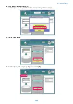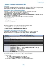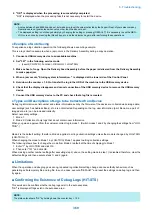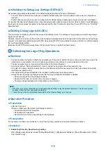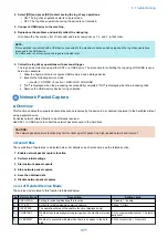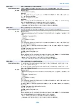
■ Initializing the Debug Log Settings (DEFAULT)
Set all debug log-related settings back to the default settings (the state at the time of shipment).
• You must perform this measure when you complete troubleshooting and return the device to the customer. (Operations
required)
• Perform this measure when you reset or make another settings relating to debug log during a log collection investigation.
For log files that were automatically stored in the debug log storage space secured in the machine's controller (/var/xpt/dbglog),
they kept to be stored unless the number of log files exceeds the limit. To delete the stored log (to use HIT-STS), use "LOG-DEL"
described later.
■ Deleting Debug Logs (LOG-DEL)
This is a function to delete log files that have been automatically stored. The settings on log operation such as the log storage
trigger are not cleared.
Normally, there is no need to use this function (the firmware automatically restricts the upper limit for the number of stored logs);
however, it is necessary to delete logs by LOG-DEL when using HIT-STS to see whether the log is collected or not after changing
the log storage trigger setting.
(Because the HIT-STS status always shows OK as long as there is a log that has been stored.)
Collecting the Log of Key Operations
■ Overview
• The key operation log function collects key operation log of the user to identify the cause of an error such as a wrong FAX
transmission, to see whether the error is caused by a failure in the machine or a wrong operation of the user.
• The key operation log is not recorded with the status at the time of shipment.
• A setting is ready in "Setting/ Registration" menu to enable the saving function of key operation log.
• Only when the above setting is enabled, the machine determines that the user permission has been obtained and starts
recording user operation log.
• User operation log is saved/collected to be included in sublog when the sublog is saved.
• Among the user operation log that was saved, the following confidential information is masked.
• Password entered from the software keyboard
• Password, PIN code, etc. entered from the numeric keypad
• Character strings displayed with turned letters on the UI screen
NOTE:
• When the log is output, information such as passwords and PINs is output as masked characters. This can help prevent
sensitive information from being leaked externally.
• Collect this log when it is determined that analysis of the firmware debug log is required.
■ Operation Procedure
● Preparation
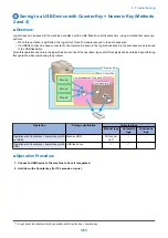
• USB memory device
Prepare a USB device that meets the following conditions.
• Formatted with the FAT file system
• Not locked with a password
• Has the firmware of the corresponding model registered
● Prerequisites
It is necessary to obtain user permission to record the log of key operations to analyze problems in advance.
● Operation
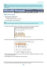
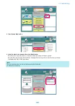
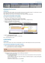
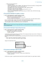
1. Enable the [Store Key Operation Log] setting.
After obtaining user permission, select [Settings/Registration] > [Management Settings] > [Device Management] > [Store
Key Operation Log].
6. Troubleshooting
370
Summary of Contents for imagerunner advance 4551i
Page 19: ...Product Overview 1 Product Lineup 7 Features 13 Specifications 16 Name of Parts 26 ...
Page 155: ...Periodical Service 3 Consumable Parts List 143 Cleaning Check Adjustment Locations 146 ...
Page 392: ...Error Jam Alarm 7 Overview 380 Error Code 383 Jam Code 509 Alarm Code 520 ...
Page 545: ...Service Mode 8 Overview 533 COPIER 549 FEEDER 845 SORTER 851 BOARD 871 ...
Page 892: ...Unpacking 1 2 1200 mm 840 mm 769 mm 1230 mm 2430 mm 3 9 Installation 879 ...
Page 895: ...3 4 NOTE Keep the removed screws for relocating the host machine 2x 5 6 7 9 Installation 882 ...
Page 896: ...8 9 10 1x Installing the Air Filter 1 9 Installation 883 ...
Page 897: ...2 3 Installing the Drum Unit 1 2 3 9 Installation 884 ...
Page 899: ...8 NOTE The screw removed at procedure 4 is used 1x 9 10 11 12 9 Installation 886 ...
Page 923: ...5 6 NOTE Use the screws and Rubber Caps removed in step 1 2x 7 2x 9 Installation 910 ...
Page 935: ...7 1x 8 9 6x 10 2x 9 Installation 922 ...
Page 936: ...11 Installing the NFC Kit 1 2 2x 3 TP M3x4 1x 9 Installation 923 ...
Page 938: ...4 5 1x 6 9 Installation 925 ...
Page 985: ...8 2x 2x TP M4x8 Black When installing the USB Keyboard 1 9 Installation 972 ...
Page 991: ...7 4x 8 1x 1x Lower Cover 9 1x 10 1x 1x 9 Installation 978 ...
Page 992: ...11 1x 1x 12 1x 13 TP M3x12 2x 14 4x TP M3x6 9 Installation 979 ...
Page 997: ...Installation Procedure 1 2 2x 3 2x 4 6x 5 4x 9 Installation 984 ...
Page 998: ...6 7 NOTE Do not close the Wire Saddle 1x 1x 8 9 9 Installation 985 ...
Page 1003: ...2 1x 1x 3 2x 2x 4 9 Installation 990 ...
Page 1012: ...2 1x 1x 3 2x 2x 4 9 Installation 999 ...
Page 1014: ...7 CAUTION The connector must be contacted TP㸹M3x6 3x 1x 8 4x 9 9 Installation 1001 ...
Page 1016: ...13 4x 14 15 Binding M4x16 Binding M3x16 2x M3x16 M4x16 16 Binding M4x6 1x 9 Installation 1003 ...
Page 1023: ...Installation Procedure Preparation 1 4x 2 1x 1x 3 2x 9 Installation 1010 ...
Page 1029: ...4 5 1x 1x 9 Installation 1016 ...
Page 1048: ...3 2x TP M3x8 Black 4 2x TP M3x6 5 9 Installation 1035 ...
Page 1053: ... Installing the Removable HDD Kit 1 2x 2x 2 3 1x 4 9 Installation 1040 ...
Page 1065: ...3 2x TP M3x8 Black 4 2x TP M3x6 5 9 Installation 1052 ...
Page 1071: ... Installing the Removable HDD Kit 1 2x 2x 2 3 1x 4 9 Installation 1058 ...

