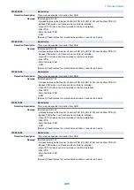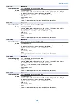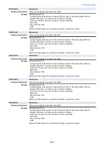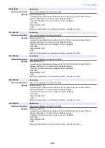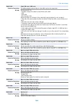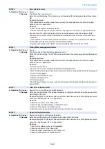
Jam Code
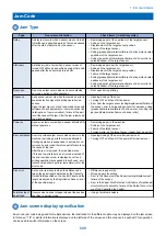
Jam Type
Type
Overview of detection
Check items (in arbitrary order)
Delay
A delay jam occurs when a sensor was not turned
ON although a specified period of time had passed
after the start of detection by the sensor.
• Remaining paper at the upstream of the target sensor
• Soiling on the target sensor
• Displacement of the target sensor position
• Failure of the target sensor
• Soiling (grease)/deterioration/failure of a drive motor located
upstream of the target sensor
• Soiling (paper dust)/deterioration/failure of a drive roller lo-
cated upstream of the target sensor
Stationary
A stationary jam occurs when a sensor was not
turned OFF although a specified period of time had
passed after the sensor was turned ON.
• Remaining paper near the target sensor
• Soiling on the target sensor
• Displacement of the target sensor position
• Failure of the target sensor
• Soiling (grease)/deterioration/failure of a drive motor located
upstream of the target sensor
• Soiling (paper dust)/deterioration/failure of a drive roller lo-
cated upstream of the target sensor
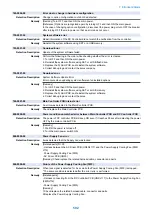
Door open
A door open jam occurs when a sensor detected
door open during printing operation.
• Door open during printing
Sequence
A sequence jam occurs when there was an error in
sensor detection signal at printing operation se-
quence.
Since the jam may occur due to sporadic noise with
software of each equipment or communication line
(interruption of communication), failure of the part
is not the cause of the jam. After the jam is removed,
the machine works.
• Opening/closing of the door
• Turning OFF and then ON the power
• Error near the target sensor (soiling/displacement/failure of
the sensor, error in harness/open circuit of harness, soiling
(grease)/deterioration/failure of a drive motor, or soiling (pa-
per dust)/deterioration/failure of a drive roller)
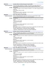
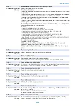
Power-on
A power-on jam occurs when a sensor detected ON
state at power-on.
• Remaining paper in the machine
• Soiling on the target sensor
• Failure of the target sensor
• Foreign matter on the target sensor (paper dust, paper lint)
Error avoidance An error avoidance jam occurs when an error in the
machine (excluding parts failure) was detected.
Printing operation is suspended to avoid error oc-
currence by error code; therefore, parts failure is not
the cause of the jam.
After the jam is removed, the machine works.
If it is due to parts failure, an error code instead of
the error avoidance jam is displayed on UI and
printing operation is suspended. In such case, serv-
ice technician should perform remedial work for the
error code.
• Opening/closing of the door after jam removal
• Turning OFF and then ON the power after jam removal
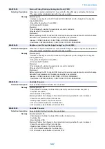
Size error
A size error jam occurs when the difference be-
tween the paper length detected by the Cassette
Guide Plate/specified on the Control Panel and the
length measured by the Registration Sensor is out
of the specified range.
• Difference in paper size
• Wrong paper size setting
• Error in the Document Size Sensor (soiling/displacement/
failure of the sensor)
• Error in the Paper Size Detection Unit (failure of mechanical
structure for size detection, failure of the Guide Plate, or fail-
ure of the Cassette Size Switch)
Forcible stop of
paper feed
It occurs when a sheet of paper stops at the position
specified in service mode.
• Using at problem analysis.
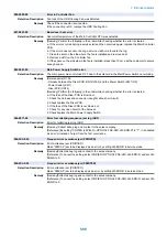
Jam screen display specification
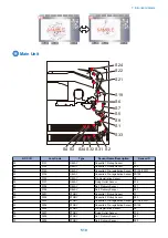
Due to one jam code being used for multiple options, the illustration for the different option may be displayed on the jam screen.
In this case, "1/2" or similar information is displayed on top left side of the screen and this area can be pushed. This operation
can be used to switch information on the screen.
7. Error/Jam/Alarm
509
Summary of Contents for imagerunner advance 4551i
Page 19: ...Product Overview 1 Product Lineup 7 Features 13 Specifications 16 Name of Parts 26 ...
Page 155: ...Periodical Service 3 Consumable Parts List 143 Cleaning Check Adjustment Locations 146 ...
Page 392: ...Error Jam Alarm 7 Overview 380 Error Code 383 Jam Code 509 Alarm Code 520 ...
Page 545: ...Service Mode 8 Overview 533 COPIER 549 FEEDER 845 SORTER 851 BOARD 871 ...
Page 892: ...Unpacking 1 2 1200 mm 840 mm 769 mm 1230 mm 2430 mm 3 9 Installation 879 ...
Page 895: ...3 4 NOTE Keep the removed screws for relocating the host machine 2x 5 6 7 9 Installation 882 ...
Page 896: ...8 9 10 1x Installing the Air Filter 1 9 Installation 883 ...
Page 897: ...2 3 Installing the Drum Unit 1 2 3 9 Installation 884 ...
Page 899: ...8 NOTE The screw removed at procedure 4 is used 1x 9 10 11 12 9 Installation 886 ...
Page 923: ...5 6 NOTE Use the screws and Rubber Caps removed in step 1 2x 7 2x 9 Installation 910 ...
Page 935: ...7 1x 8 9 6x 10 2x 9 Installation 922 ...
Page 936: ...11 Installing the NFC Kit 1 2 2x 3 TP M3x4 1x 9 Installation 923 ...
Page 938: ...4 5 1x 6 9 Installation 925 ...
Page 985: ...8 2x 2x TP M4x8 Black When installing the USB Keyboard 1 9 Installation 972 ...
Page 991: ...7 4x 8 1x 1x Lower Cover 9 1x 10 1x 1x 9 Installation 978 ...
Page 992: ...11 1x 1x 12 1x 13 TP M3x12 2x 14 4x TP M3x6 9 Installation 979 ...
Page 997: ...Installation Procedure 1 2 2x 3 2x 4 6x 5 4x 9 Installation 984 ...
Page 998: ...6 7 NOTE Do not close the Wire Saddle 1x 1x 8 9 9 Installation 985 ...
Page 1003: ...2 1x 1x 3 2x 2x 4 9 Installation 990 ...
Page 1012: ...2 1x 1x 3 2x 2x 4 9 Installation 999 ...
Page 1014: ...7 CAUTION The connector must be contacted TP㸹M3x6 3x 1x 8 4x 9 9 Installation 1001 ...
Page 1016: ...13 4x 14 15 Binding M4x16 Binding M3x16 2x M3x16 M4x16 16 Binding M4x6 1x 9 Installation 1003 ...
Page 1023: ...Installation Procedure Preparation 1 4x 2 1x 1x 3 2x 9 Installation 1010 ...
Page 1029: ...4 5 1x 1x 9 Installation 1016 ...
Page 1048: ...3 2x TP M3x8 Black 4 2x TP M3x6 5 9 Installation 1035 ...
Page 1053: ... Installing the Removable HDD Kit 1 2x 2x 2 3 1x 4 9 Installation 1040 ...
Page 1065: ...3 2x TP M3x8 Black 4 2x TP M3x6 5 9 Installation 1052 ...
Page 1071: ... Installing the Removable HDD Kit 1 2x 2x 2 3 1x 4 9 Installation 1058 ...

