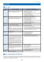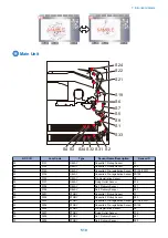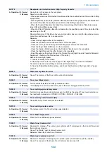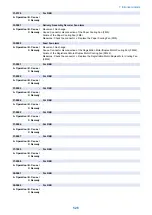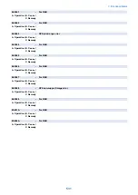
Alarm Code
Alarm Code Details
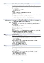
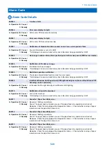
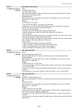
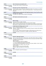
00-0085
-
A notice of stat
A. Operation / B. Cause /
C. Remedy
-
00-0246
-
Error code display (4-digit)
A. Operation / B. Cause /
C. Remedy
Soft counter PCB cannot write normally
00-0247
-
Error code display (4-digit)
A. Operation / B. Cause /
C. Remedy
Soft counter PCB cannot restore data
01-0001
-
Notification of disabled to obtain counter values for a certain period of time
A. Operation / B. Cause /
C. Remedy
Counter information is not set to UGW
* Not displayed on service mode history due to the alarm being generated by UGW
01-0002
-
No change in device status after specified period of time has passed (RDS server creates)
A. Operation / B. Cause /
C. Remedy
-
01-0004
-
Notification of IP address change
A. Operation / B. Cause /
C. Remedy
IP address has been changed
* Not displayed on service mode history due to the alarm being generated by UGW
01-0005
-
Restricted operation notification
A. Operation / B. Cause /
C. Remedy
The device entered limited function mode for some reason.
* Not displayed on service mode history due to the alarm being generated by UGW
02-0025
-
Insufficient Scanner Unit (Paper Front) LED light intensity alarm (Some of the LEDs are OFF.
Scanning can be continued.)
A. Operation / B. Cause /
C. Remedy
In the case that the light intensity is insufficient at LED lighting.
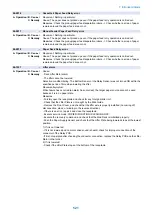
04-0010
-
Notification of jam left untouched
A. Operation / B. Cause /
C. Remedy
Jam is left untouched
* Not displayed on service mode history due to the alarm being generated by UGW
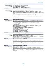
04-0011
-
Cassette 1 Paper Feed Retry error
A. Operation / B. Cause /
C. Remedy
Movement: Nothing in particular.
Cause: The paper does not picked up even if the paper feed retry operation is carried out.
Measures: Check the pick-up/paper feed/separation rollers. -> Check whether a scrap of paper
remains around the paper feed area or not.
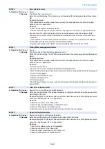
04-0012
-
Cassette 2 Paper Feed Retry error
A. Operation / B. Cause /
C. Remedy
Movement: Nothing in particular.
Cause: The paper does not picked up even if the paper feed retry operation is carried out.
Measures: Check the pick-up/paper feed/separation rollers. -> Check whether a scrap of paper
remains around the paper feed area or not.
04-0013
-
Cassette 3 Paper Feed Retry error
A. Operation / B. Cause /
C. Remedy
Movement: Nothing in particular.
Cause: The paper does not picked up even if the paper feed retry operation is carried out.
Measures: Check the pick-up/paper feed/separation rollers. -> Check whether a scrap of paper
remains around the paper feed area or not.
7. Error/Jam/Alarm
520
Summary of Contents for imagerunner advance 4551i
Page 19: ...Product Overview 1 Product Lineup 7 Features 13 Specifications 16 Name of Parts 26 ...
Page 155: ...Periodical Service 3 Consumable Parts List 143 Cleaning Check Adjustment Locations 146 ...
Page 392: ...Error Jam Alarm 7 Overview 380 Error Code 383 Jam Code 509 Alarm Code 520 ...
Page 545: ...Service Mode 8 Overview 533 COPIER 549 FEEDER 845 SORTER 851 BOARD 871 ...
Page 892: ...Unpacking 1 2 1200 mm 840 mm 769 mm 1230 mm 2430 mm 3 9 Installation 879 ...
Page 895: ...3 4 NOTE Keep the removed screws for relocating the host machine 2x 5 6 7 9 Installation 882 ...
Page 896: ...8 9 10 1x Installing the Air Filter 1 9 Installation 883 ...
Page 897: ...2 3 Installing the Drum Unit 1 2 3 9 Installation 884 ...
Page 899: ...8 NOTE The screw removed at procedure 4 is used 1x 9 10 11 12 9 Installation 886 ...
Page 923: ...5 6 NOTE Use the screws and Rubber Caps removed in step 1 2x 7 2x 9 Installation 910 ...
Page 935: ...7 1x 8 9 6x 10 2x 9 Installation 922 ...
Page 936: ...11 Installing the NFC Kit 1 2 2x 3 TP M3x4 1x 9 Installation 923 ...
Page 938: ...4 5 1x 6 9 Installation 925 ...
Page 985: ...8 2x 2x TP M4x8 Black When installing the USB Keyboard 1 9 Installation 972 ...
Page 991: ...7 4x 8 1x 1x Lower Cover 9 1x 10 1x 1x 9 Installation 978 ...
Page 992: ...11 1x 1x 12 1x 13 TP M3x12 2x 14 4x TP M3x6 9 Installation 979 ...
Page 997: ...Installation Procedure 1 2 2x 3 2x 4 6x 5 4x 9 Installation 984 ...
Page 998: ...6 7 NOTE Do not close the Wire Saddle 1x 1x 8 9 9 Installation 985 ...
Page 1003: ...2 1x 1x 3 2x 2x 4 9 Installation 990 ...
Page 1012: ...2 1x 1x 3 2x 2x 4 9 Installation 999 ...
Page 1014: ...7 CAUTION The connector must be contacted TP㸹M3x6 3x 1x 8 4x 9 9 Installation 1001 ...
Page 1016: ...13 4x 14 15 Binding M4x16 Binding M3x16 2x M3x16 M4x16 16 Binding M4x6 1x 9 Installation 1003 ...
Page 1023: ...Installation Procedure Preparation 1 4x 2 1x 1x 3 2x 9 Installation 1010 ...
Page 1029: ...4 5 1x 1x 9 Installation 1016 ...
Page 1048: ...3 2x TP M3x8 Black 4 2x TP M3x6 5 9 Installation 1035 ...
Page 1053: ... Installing the Removable HDD Kit 1 2x 2x 2 3 1x 4 9 Installation 1040 ...
Page 1065: ...3 2x TP M3x8 Black 4 2x TP M3x6 5 9 Installation 1052 ...
Page 1071: ... Installing the Removable HDD Kit 1 2x 2x 2 3 1x 4 9 Installation 1058 ...


