background image

Dec 10 2003

Installation Procedure

Finisher, Sorter, DeliveryTray
Additional Finisher Tray-A1

Summary of Contents for Inner Finisher Additional Tray-A1

Page 1: ...Dec 10 2003 Installation Procedure Finisher Sorter DeliveryTray Additional Finisher Tray A1 ...

Page 2: ......

Page 3: ... need arises In the event of major changes in the contents of this manual over a long or short period Canon will issue a new edition of this manual The following paragraph does not apply to any countries where such provisions are inconsistent with local law Trademarks The product names and company names used in this manual are the registered trademarks of the individual companies Copyright This ma...

Page 4: ...quiring care to avoid combustion fire Indicates an item prohibiting disassembly to avoid electric shocks or problems Indicates an item requiring disconnection of the power plug from the electric outlet Indicates an item intended to provide notes assisting the understanding of the topic in question Indicates an item of reference assisting the understanding of the topic in question Provides a descri...

Page 5: ...sed to indicate Low The voltage value however differs from circuit to circuit In addition the asterisk as in DRMD indicates that the DRMD signal goes on when 0 In practically all cases the internal mechanisms of a microprocessor cannot be checked in the field Therefore the operations of the microprocessors used in the machines are not discussed they are explained in terms of from sensors to the in...

Page 6: ......

Page 7: ...1 章 Installation Procedure 1 1 Making Pre Checks 2 1 1 1Checking the Contents 2 1 1 2Installing the Accessories 3 1 2 Installation Procedure 5 1 2 1Installation 5 1 3 Attaching the Labels etc 12 1 3 1Attaching the Label 12 ...

Page 8: ...Contents ...

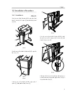
Page 9: ...Chapter 1 Installation Procedure ...

Page 10: ...ay 1 pc 7 Sensor unit 1 pc 2 Slide guide 1 pc 8 Sensor cable 1 pc 3 Front tray stay 1 pc 9 Sensor unit cover 1 pc 4 Rear tray stay 1 pc 10 Settings label 1 pc 5 Front tray stay cover 1 pc 11 Screw tapping M4x12 2 pc 6 Rear tray stay cover 1 pc 12 Screw binding M4x6 5 pc 10 2 11 3 5 12 7 12 12 11 12 9 4 6 8 1 ...

Page 11: ...n the Finisher Saddle Finisher Installation Procedure 4 Additional finisher tray 5 See the instructions herein 5 Puncher unit 6 See the Puncher Unit Installation Procedure 6 Connection to the host machine See the Finisher Saddle Finisher Installation Procedure or Connecting to the Host Machine and thereafter in the Puncher Unit Installation Procedure In the case of the Finisher R1 R2 the inner 2 w...

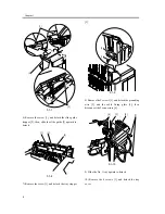
Page 12: ...Chapter 1 4 3 Disconnect the host machine s power plug from the power outlet ...

Page 13: ...e Finisher Q2 R2 open the front cover 1 F 1 4 3 In the case of the Finisher Q1 R1 remove the 3 screws 1 and detach the rear cover 2 F 1 5 4 In the case of the Saddle Finisher Q2 R2 detach the cable cover 1 remove the 6 screws 2 and detach the rear cover 3 F 1 6 5 Remove the 2 screws 1 and open the upper cover of the finisher then detach the upper left cover 3 as if to pull out the claw 2 2 2 3 1 1...

Page 14: ...to detach F 1 8 7 Remove the screw 1 and detach the tray stopper 2 F 1 9 8 Remove the 2 screws 1 and detach the grounding wire 2 and the cable fixing plate 3 then disconnect the 2 connectors 4 F 1 10 9 Slide the No 1 tray upward to detach 10 Remove the 4 screws 1 and detach the tray cover 1 2 3 1 2 3 1 2 1 2 3 4 ...

Page 15: ...er F 1 11 12 Fit the front tray stay 1 to the No 1 tray using 2 screws 2 binding M4x6 F 1 12 13 Fit the rear tray stay 1 to the No 1 tray using 2 screws 2 binding M4x6 F 1 13 14 Fit the tray cover of the No 1 tray using 4 screws The tray cover can ride over the part under it at the location indicated by the arrow be sure to pay attention to the line of alignment when fitting it F 1 14 15 Mount the...

Page 16: ...tor 4 to the sensor 5 and the another connector 6 to the connector 7 of the No 1 tray F 1 16 17 Mount the front tray stay cover 1 Using a screw 2 tapping M4x12 F 1 17 18 Mount the rear tray stay cover 1 using a screw 2 tapping M4x12 F 1 18 19 Mount the sensor unit cover 1 using a screw binding M4x6 1 2 6 2 4 7 1 5 3 1 2 2 1 ...

Page 17: ...k delivery gate comes off by accident attach it back to its home position and care should be taken not to lose the shaft spring of the stack delivery gate at this time Since the tray free falls once the latch is released hold the tray during the work F 1 20 So that there will be no discrepancy in phase between the front and rear rails you must make sure that the tray is level Move down the No 1 tr...

Page 18: ...r tray stay work as if to slide it from above the front tray stay 3 Be sure to push in the additional finisher tray until the front tray stay locks into place a click is heard F 1 22 24 Slide in the slide guide from top which is contained in the carton box to the finisher then fix the slide guide stopper removed at the step 6 in place using a screw Pay attention not to confuse the included slide g...

Page 19: ...he delivery outlet is covered when lowering the No 1 tray to near the delivery outlet Refer to the fig in step 20 27 Loosen the screw 2 on the additional finisher tray detecting plate then butt the detecting plate against the vertical face 3 of the finisher move it over 2 indexes 2 mm and fix it in place using a screw The additional finisher tray detecting plate must be fixed in place by taking me...

Page 20: ...Chapter 1 12 1 3 Attaching the Labels etc 1 3 1 Attaching the Label 0003 2138 1 Attach the Settings label 1 where indicated on the additional finisher tray F 1 25 1 m m 1 ...

Page 21: ...Dec 10 2003 ...

Page 22: ......

Reviews: