


Chapter 1
9
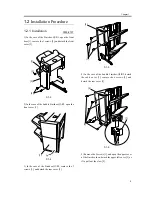
F-1-19
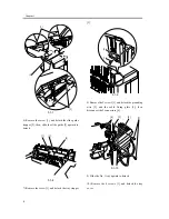
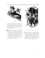
20) Attach the No. 1 tray from above, and lower it by
releasing the latch [1] at the back of the No. 1 tray. At
this time, be sure to lower the No. 1 tray while pushing
up the shutter [2] and the stack delivery gate [3] at the
delivery outlet is covered.
The stack delivery gate comes off from the finisher
when the No. 1 tray is lowered without raising the
shutter at the delivery outlet. If the stack delivery
gate comes off by accident, attach it back to its
home position, and care should be taken not to lose
the shaft spring of the stack delivery gate at this
time. Since the tray free falls once the latch is
released, hold the tray during the work.
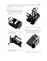
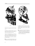
F-1-20
So that there will be no discrepancy in phase
between the front and rear rails, you must make
sure that the tray is level. Move down the No. 1 tray
as far as shown, and compare the top edge [1] of the
shutter guide and the protrusion [2] of the tray at
both front and rear; if the height is not correct,
detach the No. 1 tray once and put it back on.
[1]
[2]
[1]
[3]
[2]
Summary of Contents for Inner Finisher Additional Tray-A1
Page 1: ...Dec 10 2003 Installation Procedure Finisher Sorter DeliveryTray Additional Finisher Tray A1 ...
Page 2: ......
Page 6: ......
Page 8: ...Contents ...
Page 9: ...Chapter 1 Installation Procedure ...
Page 12: ...Chapter 1 4 3 Disconnect the host machine s power plug from the power outlet ...
Page 21: ...Dec 10 2003 ...
Page 22: ......