


Chapter 1
10
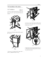
F-1-21
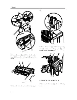
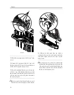
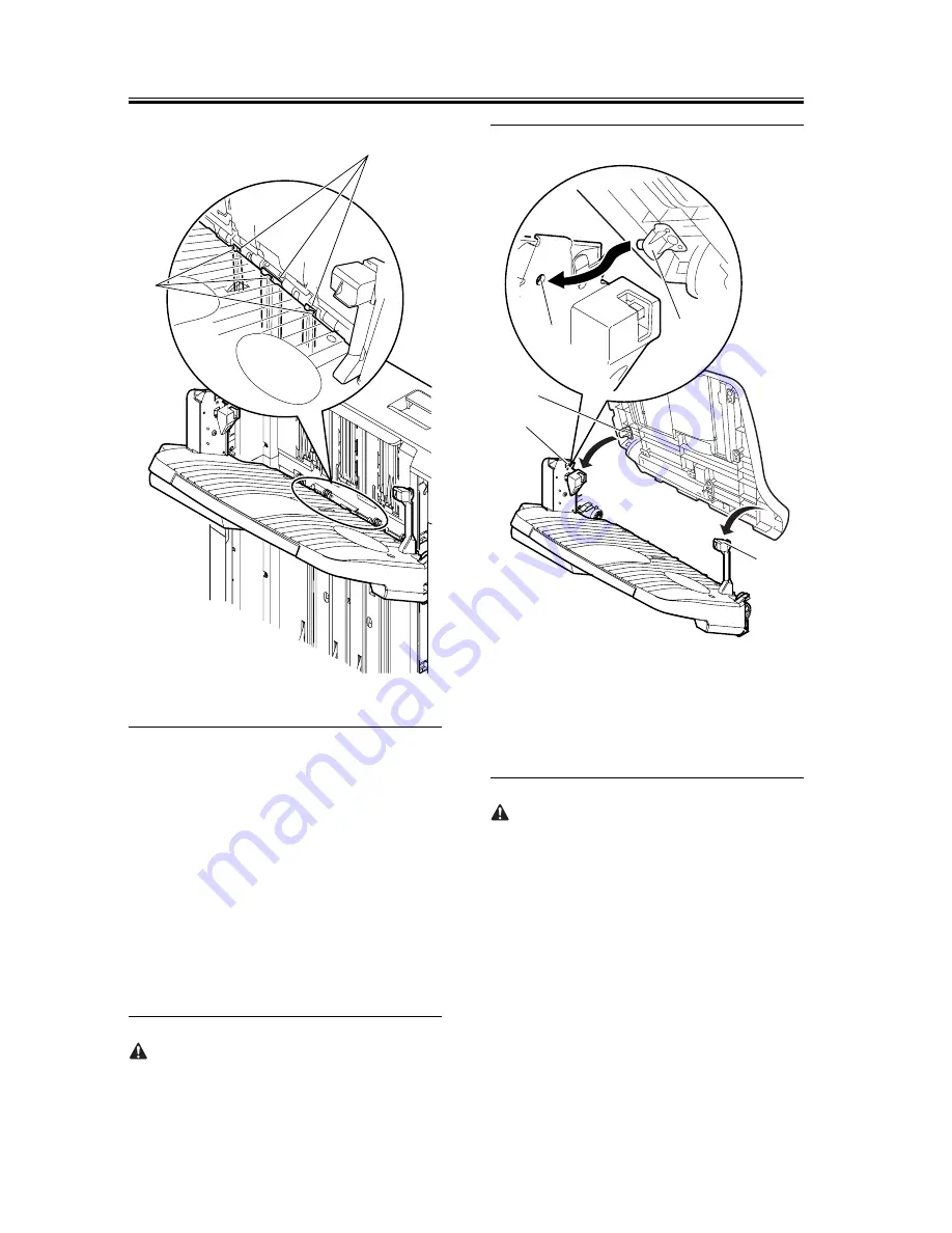
21) Mount the tray stopper removed at the step 7 using
a screw.
22) Connect the 2 connectors of the No. 1 tray to the
finisher controller PCB; then, fix the grounding wire
and the cable fixing plate using 2 screws.
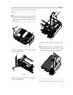
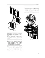
23) Mount the additional finisher tray to the tray stay
of the No. 1 tray. Fit the additional finisher tray so that
the protrusion [1] found at the joint are in the hole [2]
of the rear tray stay; work as if to slide it from above
the front tray stay [3].
Be sure to push in the additional finisher tray until
the front tray stay locks into place (a click is heard).
F-1-22
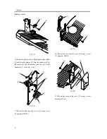
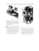
24) Slide-in the slide guide from top, which is
contained in the carton box, to the finisher; then fix the
slide guide stopper removed at the step 6 in place
using a screw.
Pay attention not to confuse the included slide
guide and the slide guide found on the finisher. The
slide guide to be used for the additional finisher tray
does not have a rib at the center. (On the other hand,
the one on the finisher has a rib.)
[1]
[2]
[2]
[3]
[1]
[2]
[1]
Summary of Contents for Inner Finisher Additional Tray-A1
Page 1: ...Dec 10 2003 Installation Procedure Finisher Sorter DeliveryTray Additional Finisher Tray A1 ...
Page 2: ......
Page 6: ......
Page 8: ...Contents ...
Page 9: ...Chapter 1 Installation Procedure ...
Page 12: ...Chapter 1 4 3 Disconnect the host machine s power plug from the power outlet ...
Page 21: ...Dec 10 2003 ...
Page 22: ......