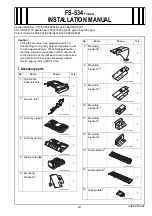
No.
Parts Name
Main Unit
Reference
Remarks
PS1
Delivery Sensor
Product Configuration
“Removing the Delivery Sensor(PS1)” on page
-
PS2
Paddle HP Sensor
Product Configuration
-
-
PS3
Return Belt HP Sensor
Product Configuration
-
-
PS4
Front Alignment Plate HP
Sensor
Processing Tray Unit
-
-
PS5
Rear Alignment Plate HP
Sensor
Processing Tray Unit
-
-
PS6
Processing Tray Paper
Sensor
Processing Tray Unit
-
-
PS7
Assist HP Sensor
Processing Tray Unit
-
-
PS8
Paper Fold HP Sensor
Processing Tray Unit
-
-
PS9
Stack Tray Paper Height
Sensor
Processing Tray Unit
-
-
PS10
Stack Tray Lower Limit
Sensor
Product Configuration
-
-
PS11
Stapler Shift HP Sensor
Product Configuration
-
-
PS12
Manual Staple Sensor
Front Cover Unit
-
-
PS13
Clinch Motor Drive Detec-
tion Sensor
Staple-free Staple Unit
-
-
PS14
Stack Tray HP Sensor
Processing Tray Unit
-
-
PS15
Clinch HP Sensor
Staple-free Staple Unit
-
-
PS17
Inlet Sensor
Product Configuration
-
-
MSW1
Front Cover Switch
Product Configuration
-
-
NOTE:
Check the operation of the part in the following service mode:
Service Mode > SITUATION > Sensor Check
List of PCBs
PCB1
PCB2
PCB3
No.
Parts Name
Main Unit
Reference
PCB1
Finisher Controller PCB
Product Configuration
“Removing the Finisher Controller PCB” on
PCB2
Stapler Relay PCB
Stapler Unit
-
PCB3
Manual Staple Switch PCB
Front Cover Unit
-
4. Disassembly/Assembly
52
Summary of Contents for Inner Finisher-J1
Page 10: ...Product Overview 1 Features 5 Specifications 6 Name of Parts 9 ...
Page 45: ...Periodical Service 3 List of Work for Scheduled Servicing 40 ...
Page 78: ...Adjustment 5 Overview 73 Adjustment when Replacing the Parts 75 Service Label 77 ...
Page 88: ...Installation Outline Drawing 1 2 3 4 5 8 9 10 11 6 7 12 6 Installation 82 ...
Page 99: ...APPENDICES Service Tools 94 General Circuit Diagram 95 ...


