Chapter 6
6-1
6.1 Troubleshooting
6.1.1 Outline
6.1.1.1 Outline of Troubleshooting
0013-1940
iPF765 / iPF760 / iPF750 / iPF755
1. Outline
Troubles subject to troubleshooting are classified into those shown on the display (warning, error, and service call) and those not shown on the display.
The code of warning and error is shown by combining alphanumeric characters of eight digits and four digits.
The code of service call error is shown by the initial character of "E" and combining alphanumeric characters of three digits and four digits.
No code number is displayed when a warning occurs. Selecting [SERVICE MODE] > [DISPLAY] > [WARNING] in service mode allows you to check the warning
log.
2. Precautions for Troubleshooting
1) Check the environmental conditions and the media used for printing.
2) Before performing troubleshooting, make sure that all connectors and cables are connected properly.
3) When servicing the printer with the external cover removed and the AC power supplied, be extremely careful to avoid electric shock and shorting electrical
devices.
4) In the following sections, the troubleshooting steps are described such that the component related to the most probable cause of the problem will be repaired or
replaced first, being followed by components with less problem probability. If multiple components have the same problem probability, the steps are described
beginning with the easiest one.
After performing each step, check to see if the problem has been resolved by making test prints. If the problem persists, proceed to the next step.
5) After completion of the troubleshooting, check that all connectors and cables have been reconnected and screws have been tightened firmly.
6) Whenever you have performed replacement or repair services, make test prints to check whether the problem has been resolved.
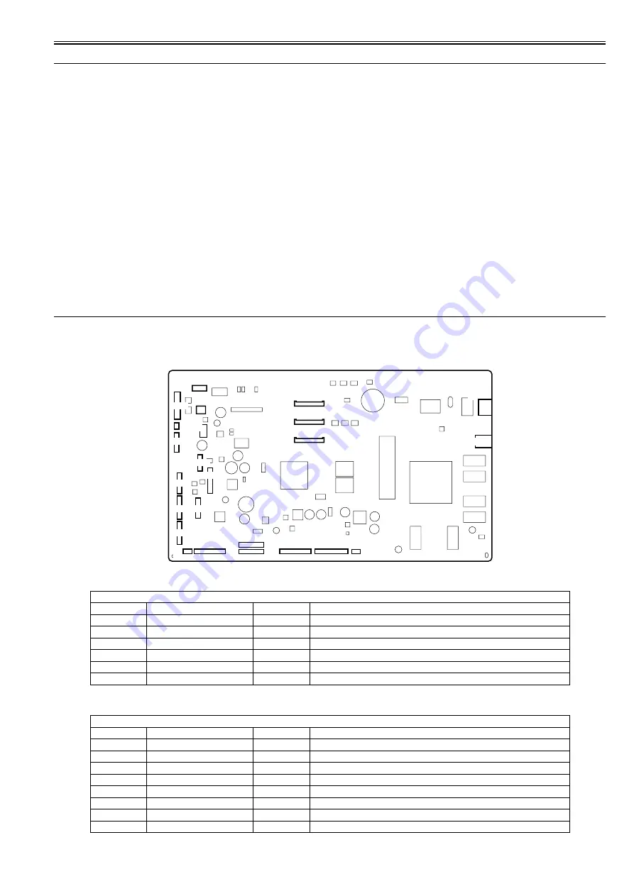
6.2 Location of Connectors and Pin Arrangement
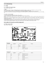
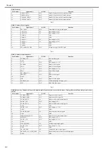
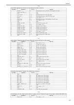
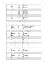
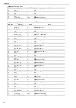
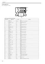
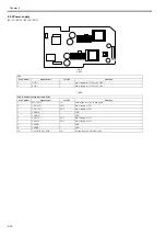
6.2.1 Main controller PCB
0023-2571
iPF765 / iPF760 / iPF750 / iPF755
F-6-1
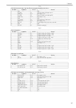
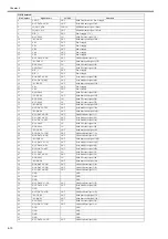
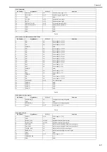
T-6-1
T-6-2
J1001 (USB)
Pin Number
Signal name
IN/OUT
Function
1
VBUS
IN
USB VBUS(+5V)
2
D-
IN/OUT
USB data (-)
3
D+
IN/OUT
USB data (+)
4
GND
-
USB GND
5
GND
-
GND (Connector shell)
6
GND
-
GND (Connector shell)
J1201 (Network)
Pin Number
Signal name
IN/OUT
Function
1
TX+
OUT
Ethernet data TX line (+)
2
TX-
OUT
Ethernet data TX line (-)
3
RX+
IN
Ethernet data RX line (+)
4
-
-
Not used
5
-
-
Not used
6
RX-
IN
Ethernet data RX line (-)
7
-
-
Not used
8
-
-
Not used
J4101
J4102
1
1
1
1
1
J3602
1
J3601
1
J3401
1
J1801
J3901
1
1
1
1
1
1
1
1
J4501
J3202J3201
J3301
J3302
J2601
J4201
J3303 J3001
1
J2951
1
J2801
1
1
J1201
J1001
Summary of Contents for iPF750 series
Page 1: ...Jul 25 2012 Service Manual iPF760 750 series ...
Page 2: ......
Page 6: ......
Page 11: ...Chapter 1 PRODUCT DESCRIPTION ...
Page 12: ......
Page 14: ...Contents 1 7 3 5 Self diagnostic Feature 1 71 1 7 3 6 Disposing of the Lithium Battery 1 72 ...
Page 87: ...Chapter 2 TECHNICAL REFERENCE ...
Page 88: ......
Page 99: ...Chapter 2 2 9 ...
Page 145: ...Chapter 3 INSTALLATION ...
Page 146: ......
Page 148: ......
Page 152: ......
Page 153: ...Chapter 4 DISASSEMBLY REASSEMBLY ...
Page 154: ......
Page 156: ......
Page 214: ...Chapter 4 4 58 2 Shaft Cleaner 1 F 4 119 1 ...
Page 215: ...Chapter 4 4 59 3 Upper Cover Hinge Catch 1 Roll Cover Slide Guide 2 F 4 120 2 1 ...
Page 218: ......
Page 219: ...Chapter 5 MAINTENANCE ...
Page 220: ......
Page 222: ......
Page 227: ...Chapter 5 5 5 ...
Page 228: ......
Page 229: ...Chapter 6 TROUBLESHOOTING ...
Page 230: ......
Page 232: ......
Page 250: ......
Page 251: ...Chapter 7 SERVICE MODE ...
Page 252: ......
Page 254: ......
Page 305: ......
Page 306: ......
Page 307: ...Chapter 8 ERROR CODE ...
Page 308: ......
Page 310: ......
Page 327: ...Jul 25 2012 ...
Page 328: ......

