Chapter 2
2-19
2.3.2.2 Ink Tank Unit
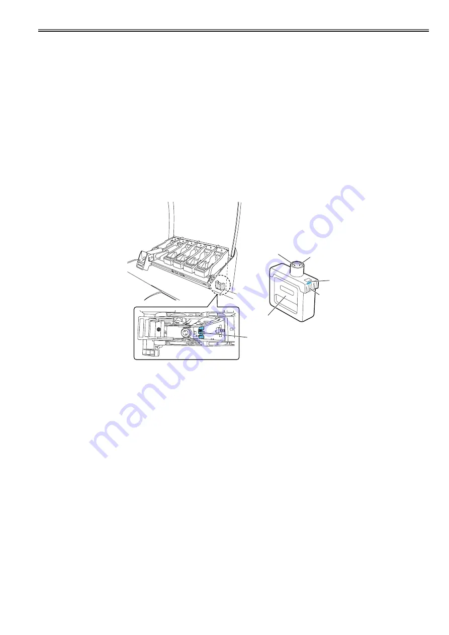
2.3.2.2.1 Structure of Ink Tank Unit
0020-5487
iPF810 / iPF820
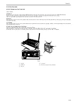
a) Ink tanks
The ink level in each ink tank is memorized in EEPROM attached to the tank and is detected as a dot count on the basis of the EEPROM information.
When an electrode attached to a hollow needle detects no continuity, it displays a message reporting that the ink tank is nearly empty.
If the dot count reaches a predesigned value in this state, an ink out condition is assumed.
b) Ink port
Depressing the ink tank fixer lever on the printer would cause would cause a hollow needle to pierce the ink tank port sealed by a rubber plug, linking the ink passage
of the ink to the printer.
c) Air passage
Depressing the ink tank fixer lever on the printer would cause an open hollow needle to pierce the air passage sealed by a rubber plug releasing the internal pressure
of the ink tank to keep it constant.
d) Notches for preventing incorrect installation
Ink tanks are furnished with a notch for preventing incorrect installation.
If the installation of an ink tank in incorrect position is attempted, the notch would interfere with it, preventing its installation.
The ink tank fixer lever won't lower without the ink tank fully inserted to reach the mounting position, so the ink cannot be supplied.
F-2-10
T-2-3
[1]
Ink tank
[4]
Air passage
[2]
EEPROM
[5]
Notch for preventing incorrect installation
[3]
Ink port
[5]
[5]
[2]
[1]
[4]
[3]
Summary of Contents for iPF800 Series
Page 1: ...Aug 13 2008 Service Manual iPF800 series ...
Page 2: ......
Page 6: ......
Page 11: ...Chapter 1 PRODUCT DESCRIPTION ...
Page 12: ......
Page 14: ......
Page 38: ...Chapter 1 1 24 Hold this lever to pull out the lower roll unit ...
Page 100: ...Chapter 1 1 86 ...
Page 101: ...Chapter 2 TECHNICAL REFERENCE ...
Page 102: ......
Page 158: ......
Page 159: ...Chapter 3 INSTALLATION ...
Page 160: ......
Page 162: ......
Page 176: ...Chapter 3 3 14 ...
Page 177: ...Chapter 4 DISASSEMBLY REASSEMBLY ...
Page 178: ......
Page 180: ......
Page 238: ...Chapter 4 4 58 ...
Page 239: ...Chapter 5 MAINTENANCE ...
Page 240: ......
Page 242: ......
Page 246: ...Chapter 5 5 4 5 Close upper cover 1 F 5 6 1 ...
Page 247: ...Chapter 5 5 5 ...
Page 248: ......
Page 249: ...Chapter 6 TROUBLESHOOTING ...
Page 250: ......
Page 252: ......
Page 274: ......
Page 275: ...Chapter 7 SERVICE MODE ...
Page 276: ......
Page 278: ......
Page 301: ......
Page 302: ......
Page 303: ...Chapter 8 ERROR CODE ...
Page 304: ......
Page 306: ......
Page 318: ...Chapter 8 8 12 ...
Page 319: ...Aug 13 2008 ...
Page 320: ......


