Chapter 2
2-32
2.3.3.2 Paper Path
2.3.3.2.1 Structure of Pick-up/Feed Unit
0020-5505
iPF810 / iPF820
a) Roll media pick-up
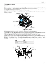
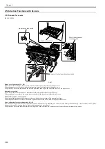
The components of the roll media pick-up consists include a pick-up roller driven by a roll media pick-up motor, a roller that follows the motion of the pick-up
roller, a roll media pick-up roller clutch that controls the driving of the pick-up roller and a roll media pick-up cam clutch that controls the rise and fall of the roller.
When the roll media detection sensor detects a roll media being loaded at the paper loading port, the roll media pick-up motor (rotating in the normal direction),
the roll media pick-up roller clutch and the roll media pick-up cam clutch turn on respectively to rotate the pick-up roller. When the roll media thus fed is detected
by the roll media pick-up roller sensor, it is moved 5 mm before it comes to a standby position.
Pressing the [OK] button on the operator console turns on the flapper solenoid, with the pick-up roller and the feed roller carrying the paper to the platen for paper
sag correction, leading paper end detection, skew detection/correction, paper width detection and more. When the paper is carried to the feed roller, the roll media
pick-up motor, roll media pick-up roller clutch and roll media pick-up cam clutch turn off to release the pick-up roller.
b) Switching between upper and lower roll media pick-up
While a roll media has been carried to the platen, if the transport of a roll media from another roll media pick-up is specified, the roll media pick-up motor (rotating
in the reverse direction), the roll media pick-up roller clutch, the roll media pick-up cam clutch and the roll media rewinding clutch turn on respectively, driving
the pick-up roller, the feed roller and the roller holder to rewind the roll media from the platen to the standby position before the transport of a roller from the other
roll media pick-up specified starts.
c) Rewinding rolls
While a roll media has been carried to the platen, if the transport of a cut form is specified, the roll media pick-up motor (rotating in the reverse direction), the roll
media pick-up roller clutch, the roll media pick-up cam clutch and the roll media rewinding clutch turn on respectively, driving the pick-up roller, the feed roller
and the roller holder to rewind the roll media from the platen to the standby position.
d) Pick-up roller sag/skew correction
When a roll media feeds, it is iteratively driven and spooled about 75mm by the pick-up roller to correct sags and skews in the roll media. If the roll media width
detection sensor detects paper (media width: about 24 inches), the roll media pick-up pressure clutch turns on to actuate the torque limiter in the roll holder drive
unit, with the result of increased back tension (about 2.6 times higher than before). The increased back tension augments the effects of sag/skew correction on wide
media.
e) Skew correction on the platen
When a roll media feeds to the platen, it is carried in the direction of paper ejection for skew detection and correction. At this time, the pinch roller pressure motor
and the pinch roller pressure clutch turn on respectively to place the pinch roller in a weakly pressurized state (under about one third of the normal pressure), thereby
reducing paper nip force acting on the feed roller for enhanced skew correction.
The status of pinch roller pressure/release is detected by the pinch roller pressure detection sensor and the pinch roller release detection sensor, with the rate of
pressurization being controlled by drives from the pinch roller pressure motor.
Skew correction on the platen is run up to three times. If skews in the roller remain uncorrected after three runs of skew correction, the roll is subjected to user skew
correction (by releasing the release lever).
Summary of Contents for iPF800 Series
Page 1: ...Aug 13 2008 Service Manual iPF800 series ...
Page 2: ......
Page 6: ......
Page 11: ...Chapter 1 PRODUCT DESCRIPTION ...
Page 12: ......
Page 14: ......
Page 38: ...Chapter 1 1 24 Hold this lever to pull out the lower roll unit ...
Page 100: ...Chapter 1 1 86 ...
Page 101: ...Chapter 2 TECHNICAL REFERENCE ...
Page 102: ......
Page 158: ......
Page 159: ...Chapter 3 INSTALLATION ...
Page 160: ......
Page 162: ......
Page 176: ...Chapter 3 3 14 ...
Page 177: ...Chapter 4 DISASSEMBLY REASSEMBLY ...
Page 178: ......
Page 180: ......
Page 238: ...Chapter 4 4 58 ...
Page 239: ...Chapter 5 MAINTENANCE ...
Page 240: ......
Page 242: ......
Page 246: ...Chapter 5 5 4 5 Close upper cover 1 F 5 6 1 ...
Page 247: ...Chapter 5 5 5 ...
Page 248: ......
Page 249: ...Chapter 6 TROUBLESHOOTING ...
Page 250: ......
Page 252: ......
Page 274: ......
Page 275: ...Chapter 7 SERVICE MODE ...
Page 276: ......
Page 278: ......
Page 301: ......
Page 302: ......
Page 303: ...Chapter 8 ERROR CODE ...
Page 304: ......
Page 306: ......
Page 318: ...Chapter 8 8 12 ...
Page 319: ...Aug 13 2008 ...
Page 320: ......


