Chapter 2
2-48
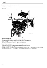
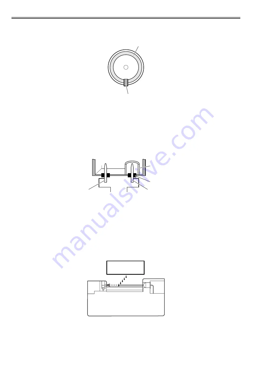
Pump encoder sensor/HP maintenance jet pump encoder sensor
The photointerrupter-based sensor reads slits in the encoder film of the Purge motor/HP maintenance jet pump motor and controls the amount of its rotaion accord-
ingly.
F-2-40
Valve open/closed detection sensor
The photointerrupter-based valve open/closed detection sensor detects the status of the valve.
The sensor detects that the ink supply valve is open when the sensor light is shielded by a flag linked with the valve cam.
Agitation cam sensor
The photointerrupter-based agitation cam sensor detects the status of the agitation cam.
The sensor detects the agitation cam home position when the sensor light allows it to be transmitted.
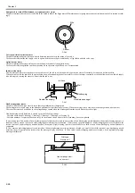
Ink detection sensor
The ink detection sensor detects the presence or absence of the ink in an ink tank with respect to the status of continuity between two hollow needles.
When the ink level in the tank falls to a point below the wall surrounding the hollow needles in the air passage, continuity with the hollow needle on the ink supply
side is disrupted, causing the sensor to detect that the ink is out.
F-2-41
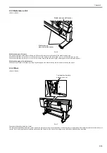
Head management sensor
The photo-transmission-type sensor detects that the printhead is discharging ink.
The carriage moves to and stops at the detection positions for individual nozzle arrays. When the carriage is at a stop, nozzles discharge ink on after another.
The sensor detects each nozzle due to the voltage change caused when ink discharged from the nozzle blocks the sensor light.
Non-discharging nozzle detection is carried out at the following timings:
- After the execution of Cleaning 1, Cleaning 2, Cleaning 3, Cleaning 6 or Cleaning 10
- After the number of copies that has been set by the user menu choice Nozzle Check Frequency have been printed
If more than a specified number of non-discharging nozzles have been located in one session of non-discharging nozzle detection, the normal cleaning sequence is
launched before a second session of non-discharging nozzle detection is conducted. If more than a specified number of non-discharging nozzles are located in the
second session of non-discharging nozzle detection, the normal (High) cleaning session is launched before a third session of non-discharging nozzle detection is
conducted.
If 30 or more non-discharging nozzles and less than 100 non-discharging nozzles per train are located as a result of the third session of non-discharging nozzle
detection, the print operation can resume after the message display as needed. If 100 or more non-discharging nozzles are located, a head replacement prompt
message is displayed.
F-2-42
Sensor
Slits
Ink tank
Wall
Rubber plug
Needle(air passage)
Needle (ink supply)
Printhead
Nozzle unit
Head management
sensor unit
Summary of Contents for iPF800 Series
Page 1: ...Aug 13 2008 Service Manual iPF800 series ...
Page 2: ......
Page 6: ......
Page 11: ...Chapter 1 PRODUCT DESCRIPTION ...
Page 12: ......
Page 14: ......
Page 38: ...Chapter 1 1 24 Hold this lever to pull out the lower roll unit ...
Page 100: ...Chapter 1 1 86 ...
Page 101: ...Chapter 2 TECHNICAL REFERENCE ...
Page 102: ......
Page 158: ......
Page 159: ...Chapter 3 INSTALLATION ...
Page 160: ......
Page 162: ......
Page 176: ...Chapter 3 3 14 ...
Page 177: ...Chapter 4 DISASSEMBLY REASSEMBLY ...
Page 178: ......
Page 180: ......
Page 238: ...Chapter 4 4 58 ...
Page 239: ...Chapter 5 MAINTENANCE ...
Page 240: ......
Page 242: ......
Page 246: ...Chapter 5 5 4 5 Close upper cover 1 F 5 6 1 ...
Page 247: ...Chapter 5 5 5 ...
Page 248: ......
Page 249: ...Chapter 6 TROUBLESHOOTING ...
Page 250: ......
Page 252: ......
Page 274: ......
Page 275: ...Chapter 7 SERVICE MODE ...
Page 276: ......
Page 278: ......
Page 301: ......
Page 302: ......
Page 303: ...Chapter 8 ERROR CODE ...
Page 304: ......
Page 306: ......
Page 318: ...Chapter 8 8 12 ...
Page 319: ...Aug 13 2008 ...
Page 320: ......


