Chapter 2
2-49
2.5.3 Carriage system
0020-5567
iPF810 / iPF820
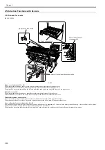
F-2-43
Printhead fixer lever sensor
The photointerrupter-type printhead fixer lever sensor detects the opening and closing of the printhead fixer lever.
When the printhead fixer lever is closed, the sensor arm shields the sensor light, causing the sensor to detect the closed state of the printhead fixer lever.
Carriage HP sensor
The photointerrupter-based carriage HP sensor detects the home position of the carriage.
Installed on the right side plate of the printer, the sensor detects an edge of the carriage home position on the carriage unit under carriage unit under carriage move-
ment control.
The printer establishes the carriage home position from the position at which its edge is detected as a reference position.
Linear encoder sensor
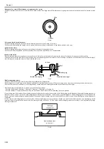
Mounted on the back of the carriage, the linear encoder detects the position of the carriage from a slit in the linear scale during its movement.
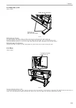
Lift cam sensor
A photointerrupter-based sensor. After the sensor light is shielded by the flag, the lift motor is driven by a predetermined number of pulses to regulate the separation
between the printheads and platen automatically.
Ambient temperature sensor
The thermostat-based ambient temperature sensor mounted on the head relay PCB detects the ambient temperature to which the carriage is exposed.
The resistance of the thermistor that varies as a function of temperature changes in the printer is transmitted to the main controller via the carriage relay PCB.
The ambient temperature is used to help calibrate the head temperature sensor and detect abnormal ambient temperatures.
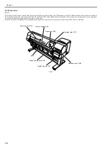
Head temperature sensor
Multi sensor
Lift cam sensor
Carriage HP sensor
Linear scale
Linear encoder sensor
Printhead fixer lever sensor
Summary of Contents for iPF800 Series
Page 1: ...Aug 13 2008 Service Manual iPF800 series ...
Page 2: ......
Page 6: ......
Page 11: ...Chapter 1 PRODUCT DESCRIPTION ...
Page 12: ......
Page 14: ......
Page 38: ...Chapter 1 1 24 Hold this lever to pull out the lower roll unit ...
Page 100: ...Chapter 1 1 86 ...
Page 101: ...Chapter 2 TECHNICAL REFERENCE ...
Page 102: ......
Page 158: ......
Page 159: ...Chapter 3 INSTALLATION ...
Page 160: ......
Page 162: ......
Page 176: ...Chapter 3 3 14 ...
Page 177: ...Chapter 4 DISASSEMBLY REASSEMBLY ...
Page 178: ......
Page 180: ......
Page 238: ...Chapter 4 4 58 ...
Page 239: ...Chapter 5 MAINTENANCE ...
Page 240: ......
Page 242: ......
Page 246: ...Chapter 5 5 4 5 Close upper cover 1 F 5 6 1 ...
Page 247: ...Chapter 5 5 5 ...
Page 248: ......
Page 249: ...Chapter 6 TROUBLESHOOTING ...
Page 250: ......
Page 252: ......
Page 274: ......
Page 275: ...Chapter 7 SERVICE MODE ...
Page 276: ......
Page 278: ......
Page 301: ......
Page 302: ......
Page 303: ...Chapter 8 ERROR CODE ...
Page 304: ......
Page 306: ......
Page 318: ...Chapter 8 8 12 ...
Page 319: ...Aug 13 2008 ...
Page 320: ......


