Chapter 2
2-50
The head temperature sensor detects the temperature of the printhead.
The printhead temperature is transmitted to the main controller via the carriage relay PCB.
The printhead temperature is used to help control the head drive and detect abnormal printhead temperatures.
Printhead contact detection
The printhead contact detects the status of printhead installation by electrical means.
The contact detects the status of contact from voltage changes in the flexible cables on the carriage side that come into contact with two terminals of the printhead
with remote contact surfaces, the power terminals and GND terminal.
Multi sensor
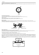
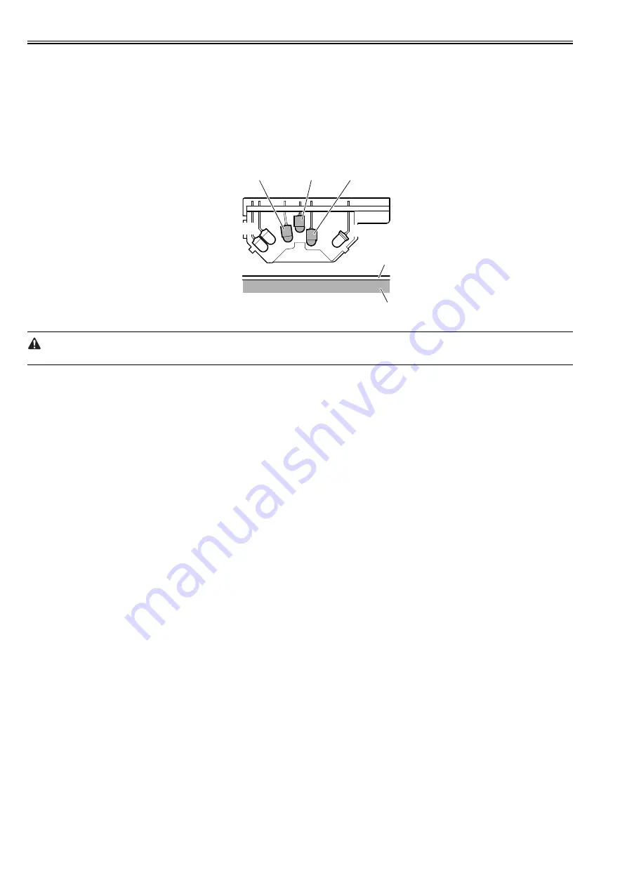
The photo-reflection-type multi sensor is composed of four LEDs (red, blue, green and infrared) and two light-sensitive sensors. It detects the leading edge, skewing,
and width of media and is used for adjustment of the registration, head height, and color calibration.
During head adjustment, the light reflected by the infrared LED and green LED is detected by two light-sensitive sensors to calculate the head height from the
difference between the measurements.
F-2-44
- Service mode: After SERVICE MODE > ADJUST > GAP CALIB. has been carried out, pass paper to make sure that it is detected properly.
Platen
Media
Infrared LED
LED(red)
LED(green)
LED(blue)
Infrared sensor
Summary of Contents for iPF800 Series
Page 1: ...Aug 13 2008 Service Manual iPF800 series ...
Page 2: ......
Page 6: ......
Page 11: ...Chapter 1 PRODUCT DESCRIPTION ...
Page 12: ......
Page 14: ......
Page 38: ...Chapter 1 1 24 Hold this lever to pull out the lower roll unit ...
Page 100: ...Chapter 1 1 86 ...
Page 101: ...Chapter 2 TECHNICAL REFERENCE ...
Page 102: ......
Page 158: ......
Page 159: ...Chapter 3 INSTALLATION ...
Page 160: ......
Page 162: ......
Page 176: ...Chapter 3 3 14 ...
Page 177: ...Chapter 4 DISASSEMBLY REASSEMBLY ...
Page 178: ......
Page 180: ......
Page 238: ...Chapter 4 4 58 ...
Page 239: ...Chapter 5 MAINTENANCE ...
Page 240: ......
Page 242: ......
Page 246: ...Chapter 5 5 4 5 Close upper cover 1 F 5 6 1 ...
Page 247: ...Chapter 5 5 5 ...
Page 248: ......
Page 249: ...Chapter 6 TROUBLESHOOTING ...
Page 250: ......
Page 252: ......
Page 274: ......
Page 275: ...Chapter 7 SERVICE MODE ...
Page 276: ......
Page 278: ......
Page 301: ......
Page 302: ......
Page 303: ...Chapter 8 ERROR CODE ...
Page 304: ......
Page 306: ......
Page 318: ...Chapter 8 8 12 ...
Page 319: ...Aug 13 2008 ...
Page 320: ......


