Chapter 4
4-57
4.5 Adjustment and Setup Items
4.5.1 Adjustment Item List
0017-8323
iPF810 / iPF820
The following adjustment procedures need to be performed when parts have been replaced or remove and then reinstalled:
T-4-3
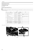
4.5.2 Procedure after Replacing the Carriage Unit or Multi Sensor
0020-5714
iPF810 / iPF820
a) Note on replacing the carriage unit and the multi sensor
The multi sensor reference plate(QL2-2840-000:MOUNT, MULTI SENSOR REFERENCE) must be replaced at the same time whenever the carriage or the multi
sensor is being replaced.
b) Multi Sensor Recalibration
Because the distance between the multi sensor (in the carriage unit) and the nozzles (in each printhead) is varied from one unit to another, the printer has its optical
axis corrected and paper gap adjustment sensor gain and calibration adjusted prior to shipment. When the carriage unit or multi sensor has been replaced, they
should require adjustment.
Execute service mode under the following conditions to launch automatic adjustment:
1) Optical axis correction
- Service mode: SERVICE MODE > ADJUST > PRINT PATTERN > OPTICAL AXIS
Media type: Gloss photo paper
2) Paper gap adjustment
- Service mode: SERVICE MODE > ADJUST > GAP CALIB.
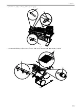
4.5.3 Procedure after Replacing the Feed Roller or Feed Roller Encoder
0012-6594
iPF810 / iPF820
Feed roller eccentricity is factory-adjusted (correction of variation in the paper feed amount per rotation). It is necessary to adjust feed roller eccentricity after re-
placing the feed roller encoder or feed roller.
In the service mode, perform automatic adjustment of feed roller eccentricity.
Service mode : SERVICE MODE > ADJUST > PRINT PATTERN > LF TUNING
Media type : Photo glossy paper
If adjustment cannot be done properly by selecting "SERVICE MODE > ADJUST > PRINT PATTERN > LF TUNING" (auto adjustment), carry out manual ad-
justment.
Service mode SERVICE MODE > ADJUST > PRINT PATTERN > LF TUNING2
Media type: Gloss photo paper
Check the printed pattern and enter values for adjustment.
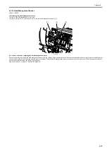
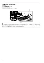
4.5.4 Procedure after Replacing the Head Management Sensor
0013-7146
iPF810 / iPF820
Since the distance between the head management sensor and the carriage unit varies among printers, the optical axis is factory-adjusted to adjust the non-discharging
detection position. When you have replaced the head management sensor or performed assembly/reassembly of surrounding parts that can change the distance be-
tween the head management sensor and the carriage unit, readjustment is required
Perform the readjustment in the service mode.
Service mode : SERVICE MODE > ADJUST > NOZZLE CHK POS.
Adjustment item
Adjustment timing
Multi sensor recalibration
Multi sensor replacement/removal
Carriage unit replacement/removal
Adjusting feed roller eccentricity
Feed roller
Feed roller encoder
Head management sensor recalibration
Head management sensor replacement/removal
Carriage unit replacement/removal
Summary of Contents for iPF800 Series
Page 1: ...Aug 13 2008 Service Manual iPF800 series ...
Page 2: ......
Page 6: ......
Page 11: ...Chapter 1 PRODUCT DESCRIPTION ...
Page 12: ......
Page 14: ......
Page 38: ...Chapter 1 1 24 Hold this lever to pull out the lower roll unit ...
Page 100: ...Chapter 1 1 86 ...
Page 101: ...Chapter 2 TECHNICAL REFERENCE ...
Page 102: ......
Page 158: ......
Page 159: ...Chapter 3 INSTALLATION ...
Page 160: ......
Page 162: ......
Page 176: ...Chapter 3 3 14 ...
Page 177: ...Chapter 4 DISASSEMBLY REASSEMBLY ...
Page 178: ......
Page 180: ......
Page 238: ...Chapter 4 4 58 ...
Page 239: ...Chapter 5 MAINTENANCE ...
Page 240: ......
Page 242: ......
Page 246: ...Chapter 5 5 4 5 Close upper cover 1 F 5 6 1 ...
Page 247: ...Chapter 5 5 5 ...
Page 248: ......
Page 249: ...Chapter 6 TROUBLESHOOTING ...
Page 250: ......
Page 252: ......
Page 274: ......
Page 275: ...Chapter 7 SERVICE MODE ...
Page 276: ......
Page 278: ......
Page 301: ......
Page 302: ......
Page 303: ...Chapter 8 ERROR CODE ...
Page 304: ......
Page 306: ......
Page 318: ...Chapter 8 8 12 ...
Page 319: ...Aug 13 2008 ...
Page 320: ......


