Chapter 1
1-23
1.5 Names and Functions of Components
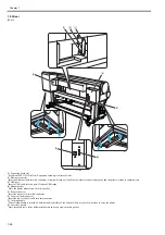
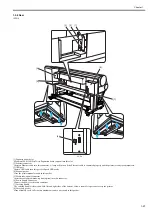
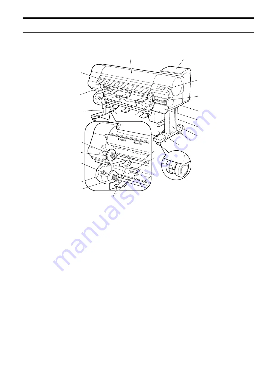
1.5.1 Front
0020-5443
iPF820
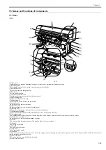
F-1-21
[1] Upper cover
Open this cover to mount a printhead, load paper or remove per jammed jams inside the printer.
[2] Ejection guides
Allow printed material to be ejected. Open these guides to load rolls.
[3] Roll Holder slot
Set the roll holder into this guide slot.
[4] Roll holder
Set a roll on this holder.
[5] Cut sheet protective cloth
A cloth tray that receives cut sheet as they are ejected.
[6] Paper loading port
Insert a roll into this port to load.
[7] Holder stopper
Use this part to secure a roll to the roll holder.
[8] Ink tank cover
Open this cover to replace ink tanks.
[9] Operation panel
Operate the printer or view its status from this panel.
[10] Release lever
Releases the paper retainer. Pull up this lever to front to load paper.
[11] Maintenance cartridge
Collects inks that have been used for maintenance services, such as head cleaning.
[12] Carrying handle
The carrying handle is located on both left and right sides of the bottom. Allow a team of six persons to carry the printer.
[13] Maintenance cartridge cover
Open this cover to replace the maintenance cartridge.
[14] Stand
The base on which the printer mounts. The stand on wheels is easy to relocate.
[15] Stand L
The left leg of the stand
[16] Stand R
The right leg of the stand.
[17] Leg cover
Cover for stands L and R.
[18] Stoppers
Clamp the wheels of the stands. Be sure to release the stoppers when relocating the printer. Moving the printer with the stoppers locked could shave the wheels,
leaving scratches on the floor surface.
[19] Lower roll unit
The unit on which a second roll media is loaded.
[20] Lower roll unit lever
[1]
[9]
[8]
[10]
[2]
[3]
[3]
[4]
[4]
[12]
[5]
[15]
[20]
[7]
[19]
[7]
[11]
[12]
[17]
[13]
[16]
[14]
[17]
[18]
[6]
Summary of Contents for iPF800 Series
Page 1: ...Aug 13 2008 Service Manual iPF800 series ...
Page 2: ......
Page 6: ......
Page 11: ...Chapter 1 PRODUCT DESCRIPTION ...
Page 12: ......
Page 14: ......
Page 38: ...Chapter 1 1 24 Hold this lever to pull out the lower roll unit ...
Page 100: ...Chapter 1 1 86 ...
Page 101: ...Chapter 2 TECHNICAL REFERENCE ...
Page 102: ......
Page 158: ......
Page 159: ...Chapter 3 INSTALLATION ...
Page 160: ......
Page 162: ......
Page 176: ...Chapter 3 3 14 ...
Page 177: ...Chapter 4 DISASSEMBLY REASSEMBLY ...
Page 178: ......
Page 180: ......
Page 238: ...Chapter 4 4 58 ...
Page 239: ...Chapter 5 MAINTENANCE ...
Page 240: ......
Page 242: ......
Page 246: ...Chapter 5 5 4 5 Close upper cover 1 F 5 6 1 ...
Page 247: ...Chapter 5 5 5 ...
Page 248: ......
Page 249: ...Chapter 6 TROUBLESHOOTING ...
Page 250: ......
Page 252: ......
Page 274: ......
Page 275: ...Chapter 7 SERVICE MODE ...
Page 276: ......
Page 278: ......
Page 301: ......
Page 302: ......
Page 303: ...Chapter 8 ERROR CODE ...
Page 304: ......
Page 306: ......
Page 318: ...Chapter 8 8 12 ...
Page 319: ...Aug 13 2008 ...
Page 320: ......

