Chapter 4
4-28
4.3.12 Head Management Sensor
0014-8988
a) Removing the head management sensor
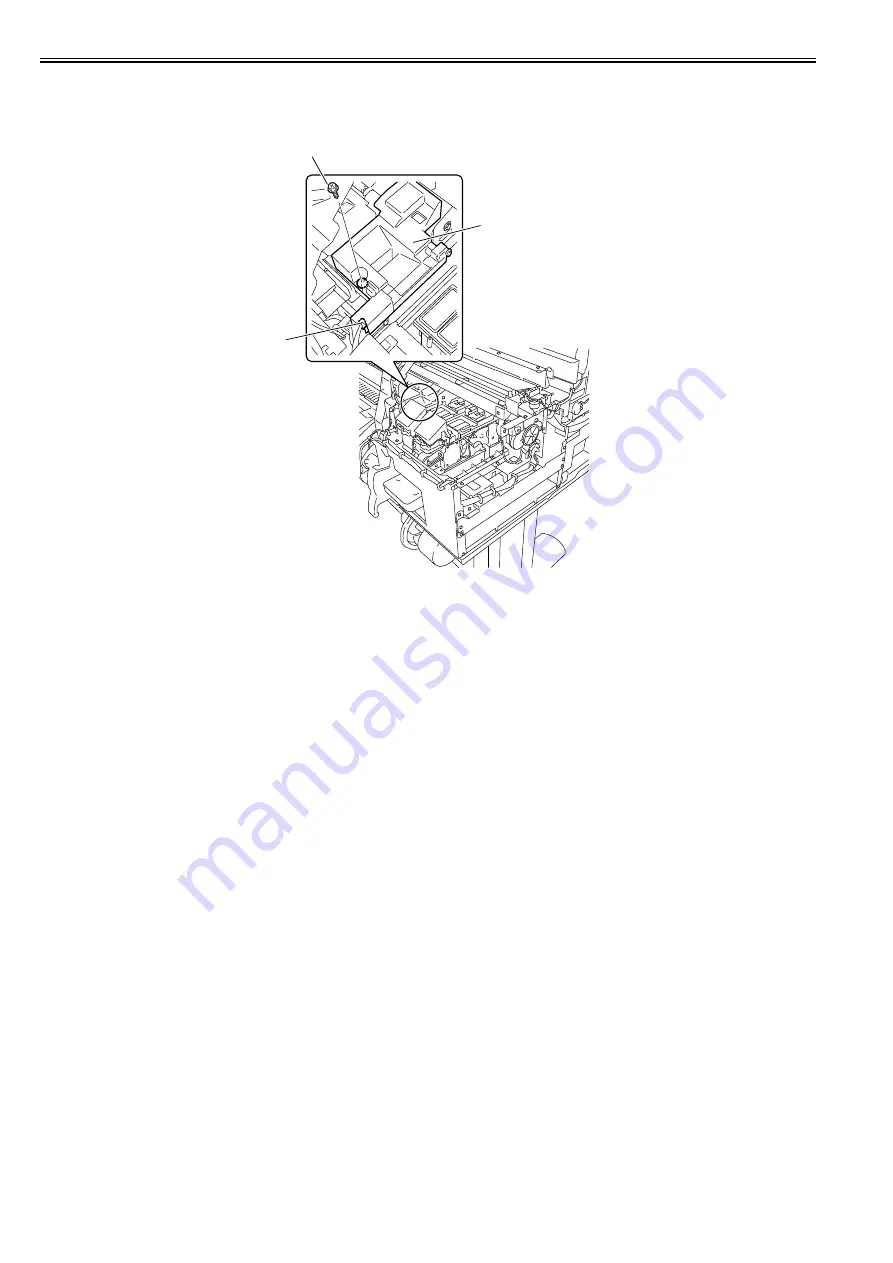
1) Remove the screw [2] and disconnect the connector [3] to remove the head management sensor [1].
F-4-47
b) Action to take after replacing the head management sensor
Because the distance between the head management sensor and the carriage unit is varied from one unit to another, the printer has its optical axis corrected to adjust
the non-discharging nozzle detection position prior to shipment. When the head management sensor has been replaced, it should require adjustment.
Execute service mode under the following conditions:
SERVICE MODE > ADJUST > NOZZLE CHK POS.
[3]
[2]
[1]
Summary of Contents for iPF8400S Series
Page 1: ...Feb 27 2017 Service Manual iPF8000 series iPF8400S ...
Page 2: ......
Page 6: ......
Page 11: ...Chapter 1 PRODUCT DESCRIPTION ...
Page 12: ......
Page 14: ......
Page 63: ...Chapter 2 TECHNICAL REFERENCE ...
Page 64: ......
Page 106: ......
Page 107: ...Chapter 3 INSTALLATION ...
Page 108: ......
Page 110: ......
Page 123: ...Chapter 3 3 13 F 3 22 6 FAN UNIT A ...
Page 125: ...Chapter 3 3 15 ...
Page 126: ......
Page 127: ...Chapter 4 DISASSEMBLY REASSEMBLY ...
Page 128: ......
Page 130: ......
Page 167: ...Chapter 4 4 37 ...
Page 168: ......
Page 169: ...Chapter 5 MAINTENANCE ...
Page 170: ......
Page 172: ......
Page 177: ...Chapter 6 TROUBLESHOOTING ...
Page 178: ......
Page 180: ......
Page 215: ...Chapter 7 SERVICE MODE ...
Page 216: ......
Page 218: ......
Page 272: ...Chapter 7 7 54 ...
Page 273: ...Chapter 8 ERROR CODE ...
Page 274: ......
Page 276: ......
Page 311: ...Feb 27 2017 ...
Page 312: ......


