Chapter 2
2-32
2.4.5 Motor Driver
2.4.5.1 Media take-up PCB components
0014-2480
F-2-28
a) Driver IC (IC104)
Media take-up motor drive function
This function controls the Media take-up motor based on the control signals from the main controller.
Sensor relay function
This function relays the input signals from the Media take-up paper detection sensor and Media take-up on/off sensor to the main controller PCB.
2.4.6 Maintenance Cartridge Relay PCB
2.4.6.1 Maintenance cartridge relay PCB components
0013-6532
F-2-29
a) EEPROM (IC1)
The 2-KB EEPROM stores all information written in the EEPROM on the main controller PCB.
2.4.7 Power Supply
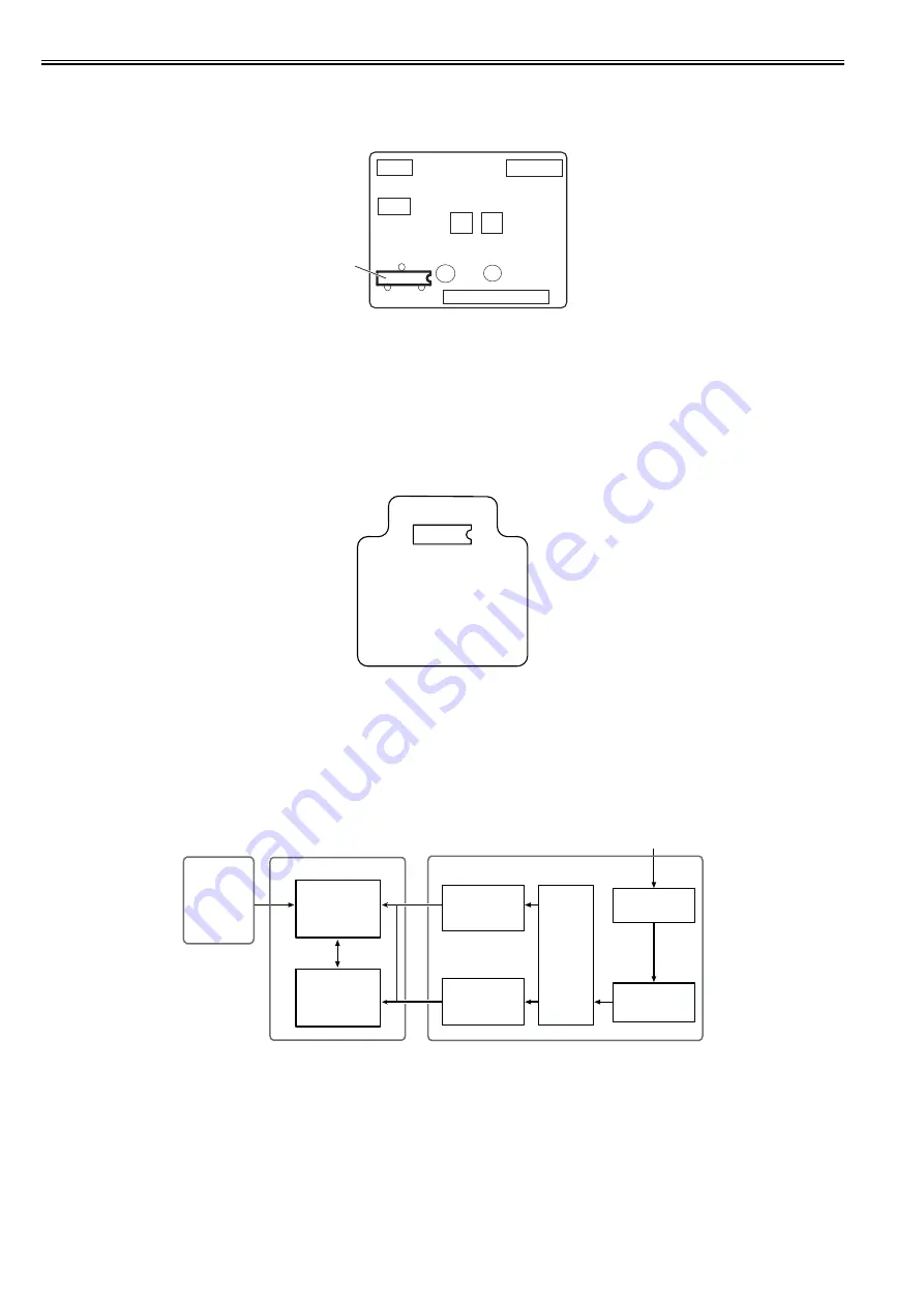
2.4.7.1 Power supply block diagram
0012-6414
F-2-30
The power supply converts AC voltages ranging from 100V to 240V from the AC inlet to DC voltages for driving the ICs, motor, and others.
The voltage generator circuits include the +32V generation circuit for driving motors, fans, and the +5.1V generator circuit for driving sensors, logic circuits.
When in the power saving mode, the power supply cut out the +32V and the +5.1V.
Power ON/OFF operation is controlled by the main controller PCB. When the upper cover is open, the power supply cut out only the +32V power to the carriage.
IC104
IC 1
Operation panel
Transformer
DC power supply
control circuit
+5.1V
generation circuit
+32V
generation circuit
POWER ON
Rectifying circuit
Noize filter circuit
AC inlet
100V to 240V
Power supply
Main controller PCB
+5V/+3.3V
generation circuit
Summary of Contents for iPF8400S Series
Page 1: ...Feb 27 2017 Service Manual iPF8000 series iPF8400S ...
Page 2: ......
Page 6: ......
Page 11: ...Chapter 1 PRODUCT DESCRIPTION ...
Page 12: ......
Page 14: ......
Page 63: ...Chapter 2 TECHNICAL REFERENCE ...
Page 64: ......
Page 106: ......
Page 107: ...Chapter 3 INSTALLATION ...
Page 108: ......
Page 110: ......
Page 123: ...Chapter 3 3 13 F 3 22 6 FAN UNIT A ...
Page 125: ...Chapter 3 3 15 ...
Page 126: ......
Page 127: ...Chapter 4 DISASSEMBLY REASSEMBLY ...
Page 128: ......
Page 130: ......
Page 167: ...Chapter 4 4 37 ...
Page 168: ......
Page 169: ...Chapter 5 MAINTENANCE ...
Page 170: ......
Page 172: ......
Page 177: ...Chapter 6 TROUBLESHOOTING ...
Page 178: ......
Page 180: ......
Page 215: ...Chapter 7 SERVICE MODE ...
Page 216: ......
Page 218: ......
Page 272: ...Chapter 7 7 54 ...
Page 273: ...Chapter 8 ERROR CODE ...
Page 274: ......
Page 276: ......
Page 311: ...Feb 27 2017 ...
Page 312: ......


