Chapter 6
6-11
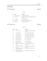
6.7
PCBs
6.7.1
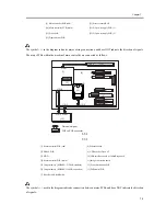
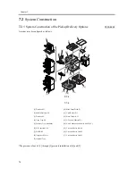
Reader Unit
0001-0442
T-6-10
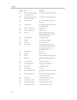
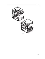
6.7.2
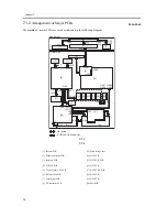
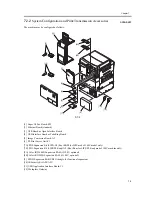
Printer Unit
0001-0448
T-6-11
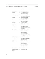
Ref.
Name
Description
[1]
reader controller PCB
controls the reader unit/ADF.
[2]
interface PCB
communicates image information read by the reader unit to
the printer unit.
[3]
inverter PCB
controls the scanning lamp.
[4]
CCD/AP PCB
drives the CCD/processes analog images.
[5]
fuse PCB
controls mirrors/lens heater.
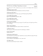
Notation
Name
Description
[6]
DC controller PCB
controls the power supply to the printer unit/
accessories
[7]
Laser driver PCB (Y)
controls the drive of the laser unit (Y)
[8]
Laser driver PCB (M)
controls the drive of the laser unit (M)
[9]
Laser driver PCB (C)
controls the drive of the laser unit (C)
[10]
Laser driver PCB (Bk)
controls the drive of the laser unit (Bk)
[11]
BD detection PCB (Y)
detects the laser beam (Y)
[12]
BD detection PCB (M)
detects the laser beam (M)
[13]
BD detection PCB (C)
detects the laser beam (C)
[14]
BD detection PCB (Bk)
detects the laser beam (Bk)
[15]
Waste toner detection PCB (light-
emitting)
detects the level of toner inside the waste
toner container
[16]
Waste toner detection PCB (light-
receiving)
detects the level of toner inside the waste
toner container
[17]
Auto registration sensor F (light-
emitting) detection PCB
reads the image position correction pattern
[18]
Auto registration sensor F (light-
receiving) detection PCB
reads the image position correction pattern
Summary of Contents for iR C3200 Series
Page 1: ...Dec 3 2004 Portable Manual iR C3200 Series iR C3220N PRT ...
Page 2: ......
Page 6: ......
Page 10: ......
Page 11: ...Chapter 1 Maintenance and Inspection ...
Page 12: ......
Page 14: ......
Page 22: ...Chapter 1 1 8 ...
Page 23: ...Chapter 2 Standards and Adjustments ...
Page 24: ......
Page 26: ......
Page 40: ...Chapter 2 2 14 ...
Page 41: ...Chapter 3 Error Code ...
Page 42: ......
Page 43: ...Contents Contents 3 1 Error Code Details 3 1 3 1 1 Error Code Details Table 3 1 ...
Page 44: ......
Page 63: ...Chapter 4 User Mode Items ...
Page 64: ......
Page 66: ......
Page 79: ...Chapter 5 Service Mode ...
Page 80: ......
Page 82: ......
Page 121: ...Chapter 6 Outline of Components ...
Page 122: ......
Page 124: ......
Page 134: ...Chapter 6 6 10 F 6 6 PLG1 ELCB1 SP1 H4 H3 H2 H1 H1 H2 LA1 ...
Page 138: ...Chapter 6 6 14 ...
Page 139: ...Chapter 7 System Construction ...
Page 140: ......
Page 142: ......
Page 157: ...Chapter 8 Upgrading ...
Page 158: ......
Page 160: ......
Page 168: ...Chapter 8 8 8 ...
Page 169: ...Dec 3 2004 ...
Page 170: ......


