Chapter 7
7-5
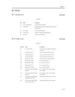
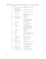
7.2.2
System Configuration and Print/Transmission Accessories
0006-8287
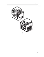
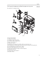
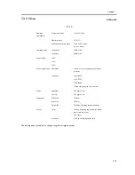
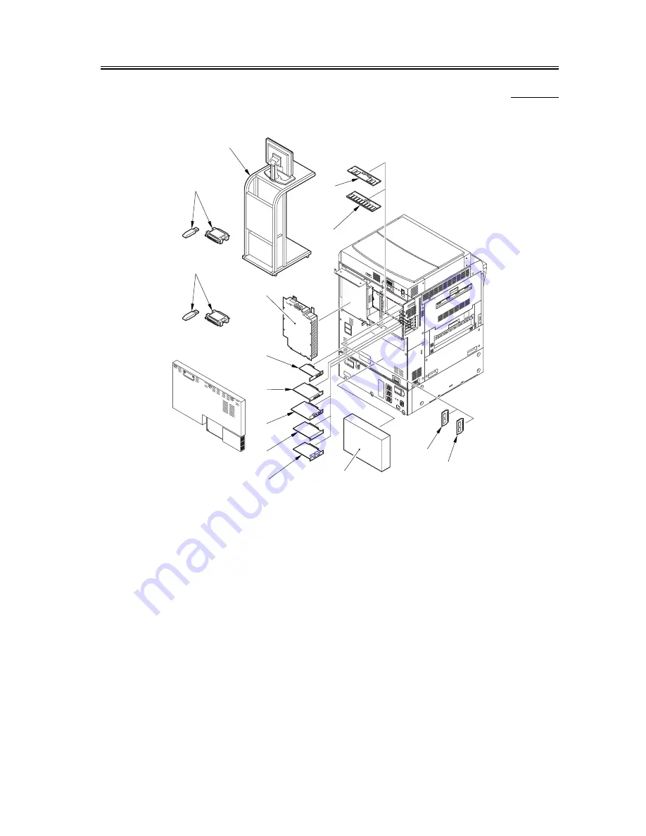
The machine may be configured as follows:
F-7-5
[1] Super G3 Fax Board-M2
[2] Ethernet Board (standard)
[3] UFR Board or Open Interface Board
[4] USB Interface Board or TokeRing Board
[5] Image Conversion Board-A2
[6] PS Print Server Unit-C1
[7A] PDL Expansion Kit (LIPS)-A2 (boot ROM for LIPS model: 100V model only)
[7B] PDL Expansion Kit (LIPS/PS Kanji) A2 (Boot Rom for LIPS/PS Kanji model: 100V machine only)
[8A] Color iR256 MB Expansion RAM (if 100V, optional)
[8B] Color iR512MB Expansion RAM (if 100V, optional)
[9] SEND Expansion Kit-B2/B2U (dongle for functional expansion)
[10] iR Security Kit-A2P/A2U
[11] USB Application Interface Board-C1
[12] Workplase Gateway
[1]
[2]
[3]
[4]
[5]
[11]
[12]
[10]
[7A]
[7B]
[6]
[9]
[8A]
[8B]
Summary of Contents for iR C3200 Series
Page 1: ...Dec 3 2004 Portable Manual iR C3200 Series iR C3220N PRT ...
Page 2: ......
Page 6: ......
Page 10: ......
Page 11: ...Chapter 1 Maintenance and Inspection ...
Page 12: ......
Page 14: ......
Page 22: ...Chapter 1 1 8 ...
Page 23: ...Chapter 2 Standards and Adjustments ...
Page 24: ......
Page 26: ......
Page 40: ...Chapter 2 2 14 ...
Page 41: ...Chapter 3 Error Code ...
Page 42: ......
Page 43: ...Contents Contents 3 1 Error Code Details 3 1 3 1 1 Error Code Details Table 3 1 ...
Page 44: ......
Page 63: ...Chapter 4 User Mode Items ...
Page 64: ......
Page 66: ......
Page 79: ...Chapter 5 Service Mode ...
Page 80: ......
Page 82: ......
Page 121: ...Chapter 6 Outline of Components ...
Page 122: ......
Page 124: ......
Page 134: ...Chapter 6 6 10 F 6 6 PLG1 ELCB1 SP1 H4 H3 H2 H1 H1 H2 LA1 ...
Page 138: ...Chapter 6 6 14 ...
Page 139: ...Chapter 7 System Construction ...
Page 140: ......
Page 142: ......
Page 157: ...Chapter 8 Upgrading ...
Page 158: ......
Page 160: ......
Page 168: ...Chapter 8 8 8 ...
Page 169: ...Dec 3 2004 ...
Page 170: ......


