Chapter 3
3-5
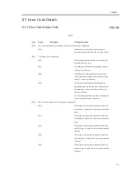
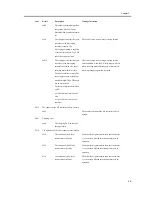
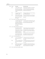
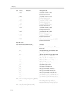
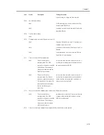
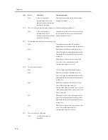
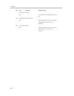
xxB2
The value is extremely high when
compared with the T/D ratio
detected when a new drum unit is
set.
xxC0
The supply of toner for the toner
container to the developing
assembly is faulty. The
developing assembly is supplied
with toner excessively. The ATR
sensor has an open circuit.
The fault occurs when an image is being formed.
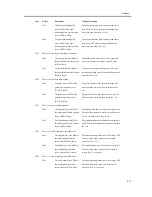
xxD0
The supply of toner for the toner
container to the developing
assembly has failed. The toner
cartridge motor fails to rotate.
The toner container is empty. The
toner supply mouth of the drum
unit is damaged. The ATR sensor
has an open circuit.
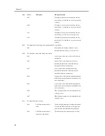
For the first 2 digits of detail code
xxEE,
xx=00: fault in access to drum
unit
xx=01: fault in access to toner
container
The fault occurs when an image is being formed
and, in addition, when the T/D ratio drops while 20
prints are being made continuously. It is detected
when toner supply operation is started.
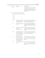
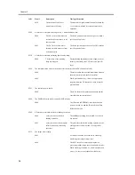
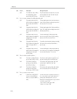
E032
The counter of the NE controller fails to operate.
0000
The counter function of the NE controller fails to
operate.
E061
Charging error
xxdd
The charging DC bias exceeds
the upper limit.
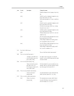
E110
The operation of the laser scanner motor is faulty.
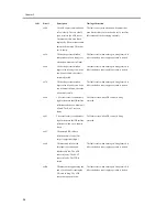
0110
The rotation of the Y laser
scanner motor is faulty.
The motor lock signal remains in an unlock state for
1 sec or more while the laser scanner motor is in
operation.
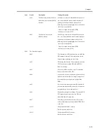
0210
The rotation of the M laser
scanner motor is faulty.
The motor lock signal remains in an unlock state for
1 sec or more while the laser scanner motor is in
operation.
0310
The rotation of the C laser
scanner motor is faulty.
The motor lock signal remains in an unlock state for
1 sec or more while the laser scanner motor is in
operation.
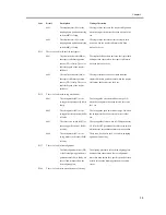
Code
Detail
Description
Timing of detection
Summary of Contents for iR C3200 Series
Page 1: ...Dec 3 2004 Portable Manual iR C3200 Series iR C3220N PRT ...
Page 2: ......
Page 6: ......
Page 10: ......
Page 11: ...Chapter 1 Maintenance and Inspection ...
Page 12: ......
Page 14: ......
Page 22: ...Chapter 1 1 8 ...
Page 23: ...Chapter 2 Standards and Adjustments ...
Page 24: ......
Page 26: ......
Page 40: ...Chapter 2 2 14 ...
Page 41: ...Chapter 3 Error Code ...
Page 42: ......
Page 43: ...Contents Contents 3 1 Error Code Details 3 1 3 1 1 Error Code Details Table 3 1 ...
Page 44: ......
Page 63: ...Chapter 4 User Mode Items ...
Page 64: ......
Page 66: ......
Page 79: ...Chapter 5 Service Mode ...
Page 80: ......
Page 82: ......
Page 121: ...Chapter 6 Outline of Components ...
Page 122: ......
Page 124: ......
Page 134: ...Chapter 6 6 10 F 6 6 PLG1 ELCB1 SP1 H4 H3 H2 H1 H1 H2 LA1 ...
Page 138: ...Chapter 6 6 14 ...
Page 139: ...Chapter 7 System Construction ...
Page 140: ......
Page 142: ......
Page 157: ...Chapter 8 Upgrading ...
Page 158: ......
Page 160: ......
Page 168: ...Chapter 8 8 8 ...
Page 169: ...Dec 3 2004 ...
Page 170: ......


