Chapter 3
3-3
3.2 Basic Sequence
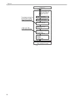
3.2.1 Basic Sequence of Operations at Power-On
0014-1417
/ / / / iR C3380i / iR C3380 / iR C2880i / iR C2880
The following shows the machine's power-on sequence in the form of a flow chart, during which the various machine loads are initialized according to the instruc-
tions programmed in the machine firmware (from when the power switch is turned on to when the machine enters a standby state):
F-3-3
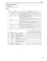
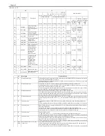
3.2.2 Basic Sequence of Operations for a Print Job (full color)
0014-1419
/ / / / iR C3380i / iR C3380 / iR C2880i / iR C2880
Full color, A4, 1 copy, Cassette 1
T-3-1
Period
Description
PSTBY (print standby)
when the machine is ready to accept a copy/print request signal.
PINTR (initial rotation)
from when a print request signal is received to when an image signal is generated.
from when all toner has been transferred to paper and the paper is delivered.
LSTR (last rotation)
from when the paper has been delivered to when all drive has been stopped.
Power-on
CPU initialization
ASIC initialization
Fan drive
Printer ID check
Fault CHK
Machine inside
residual paper/
door open check
Waste toner case presence/
absence and state (full) detection
Inside/outside machine temperature detection
Scanner motor initial drive
check
Motor drive
Waste toner supply shutter state
(open/closed) detection
BD correction control
Drum cartridge detection
Drum life detection
Toner cartridge detection
Toner level detection
(drum/ITB motor, development motor,
waste toner feed motor, fixing motor,
pickup motor, duplexing motor,
registration motor)
If within dashed lines, only when necessary.
Standby
D-max control
D-half control
ATR control
Color displacement control
ATVC control
Drum film thickness detection
ARCDAT control
Image stabilization control
1
1
Summary of Contents for iR C3380 series
Page 1: ...Aug 29 2006 Service Manual iR C3380 2880 Series...
Page 2: ......
Page 6: ......
Page 23: ...Chapter 1 Introduction...
Page 24: ......
Page 26: ......
Page 52: ......
Page 53: ...Chapter 2 Installation...
Page 54: ......
Page 127: ...Chapter 3 Basic Operation...
Page 128: ......
Page 130: ......
Page 136: ......
Page 137: ...Chapter 4 Main Controller...
Page 138: ......
Page 160: ......
Page 161: ...Chapter 5 Original Exposure System...
Page 162: ......
Page 188: ...Chapter 5 5 24 F 5 68 4 Remove the original sensor 2 hook 1 F 5 69...
Page 189: ...Chapter 6 Laser Exposure...
Page 190: ......
Page 192: ......
Page 206: ......
Page 207: ...Chapter 7 Image Formation...
Page 208: ......
Page 256: ......
Page 257: ...Chapter 8 Pickup Feeding System...
Page 258: ......
Page 262: ......
Page 303: ...Chapter 9 Fixing System...
Page 304: ......
Page 306: ......
Page 321: ...Chapter 10 Externals and Controls...
Page 322: ......
Page 326: ......
Page 336: ...Chapter 10 10 10 F 10 10 2 Remove the check mark from SNMP Status Enabled...
Page 337: ...Chapter 10 10 11 F 10 11...
Page 359: ...Chapter 11 MEAP...
Page 360: ......
Page 362: ......
Page 401: ...Chapter 12 RDS...
Page 402: ......
Page 404: ......
Page 411: ...Chapter 13 Maintenance and Inspection...
Page 412: ......
Page 414: ......
Page 416: ...Chapter 13 13 2 F 13 1 8 9 1 2 3 3 5 6 7 10 11 12 13 14 4...
Page 421: ...Chapter 14 Standards and Adjustments...
Page 422: ......
Page 424: ......
Page 431: ...Chapter 15 Correcting Faulty Images...
Page 432: ......
Page 434: ......
Page 459: ...Chapter 16 Self Diagnosis...
Page 460: ......
Page 462: ......
Page 481: ...Chapter 17 Service Mode...
Page 482: ......
Page 484: ......
Page 571: ...Chapter 18 Upgrading...
Page 572: ......
Page 574: ......
Page 603: ...Chapter 19 Service Tools...
Page 604: ......
Page 606: ......
Page 609: ...Aug 29 2006...
Page 610: ......


