Chapter 4
4-7
4.5 Image Processing
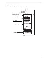
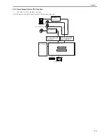
4.5.1 Overview of the Flow of Image Data
0013-9214
/ / / / iR C3380i / iR C3380 / iR C2880i / iR C2880
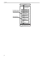
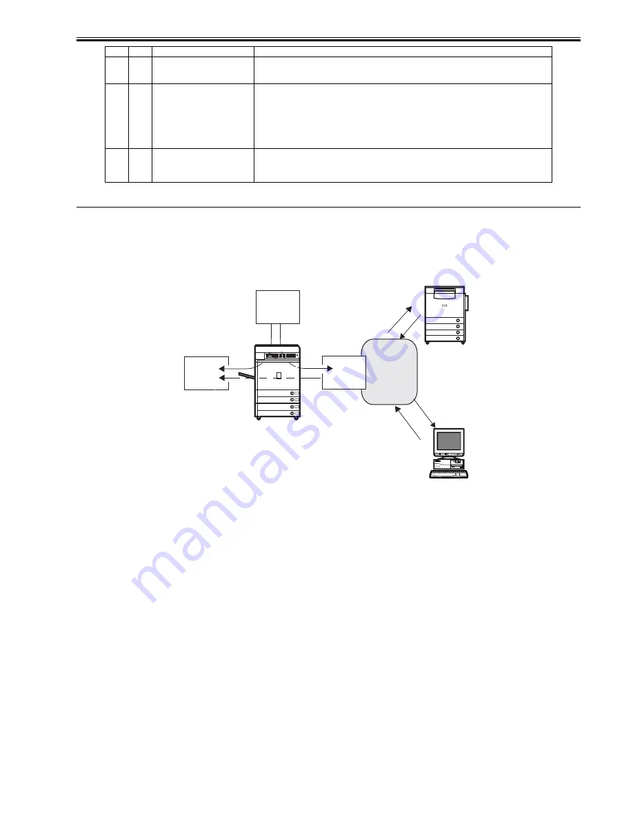
The image data processing flow useing this machine as follows;
F-4-7
4.5.2 Reader Input Image Processing
0013-9215
/ / / / iR C3380i / iR C3380 / iR C2880i / iR C2880
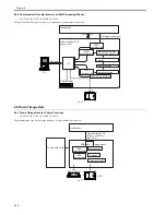
The image data (RGB data) collected by the CCD is processed by the main controller PCB (sub SJ-A, sub R-A, sub PDRM-PE-A).
*10
11,21
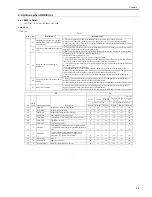
HDD contact fault
This error seldom occurs in the course of normal read/write operations.
1. Check the cable and power connectors.
2. If the foregoing fails, suspect a fault on the HDD, and replace the HDD and reinstall the system software.
*11
13,25
WriteAbort
The text file on the HDD (e.g., Box) may be damaged.
1. Indicate the partition for CHK-TYPE, and execute HDD-CHECK (several min to several 10s of min); then,
turn off and then on the power.
2. If the forgoing fails, indicate the partition for CHK-TYPE, and execute HDD-CLEAR; then, turn off and
then on the main switch.
(In the case of BOOTDEV, BOOTDEV2, or APL_SEND, execute formatting using the SST and reinstall the
system software.)
3. If the foregoing fails, suspect a fault on the HDD, and replace the HDD and reinstall the system software.
*12
10,12,
14
22,23,
24
system error, or packet data error
This error occurs in response to corruption of data or a bug in software.
1. Start up in safe mode, and execute full formatting using the SST and reinstall the system software (System,
Lang, RUI); then, turn off and then on the main power switch.
2. If the foregoing fails, suspect a fault on the HDD; replace the HDD, and reinstall the system software.
YY
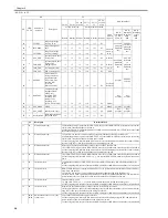
Description
Remedial action
•
SEND
•
FAX
•
PullScan
•
• BOX
• PDL Print
PC
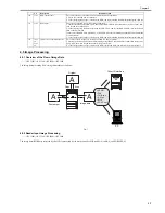
Original
Copy
A
A
A
Print output
Scan
Image data
Other iR machine
Summary of Contents for iR C3380 series
Page 1: ...Aug 29 2006 Service Manual iR C3380 2880 Series...
Page 2: ......
Page 6: ......
Page 23: ...Chapter 1 Introduction...
Page 24: ......
Page 26: ......
Page 52: ......
Page 53: ...Chapter 2 Installation...
Page 54: ......
Page 127: ...Chapter 3 Basic Operation...
Page 128: ......
Page 130: ......
Page 136: ......
Page 137: ...Chapter 4 Main Controller...
Page 138: ......
Page 160: ......
Page 161: ...Chapter 5 Original Exposure System...
Page 162: ......
Page 188: ...Chapter 5 5 24 F 5 68 4 Remove the original sensor 2 hook 1 F 5 69...
Page 189: ...Chapter 6 Laser Exposure...
Page 190: ......
Page 192: ......
Page 206: ......
Page 207: ...Chapter 7 Image Formation...
Page 208: ......
Page 256: ......
Page 257: ...Chapter 8 Pickup Feeding System...
Page 258: ......
Page 262: ......
Page 303: ...Chapter 9 Fixing System...
Page 304: ......
Page 306: ......
Page 321: ...Chapter 10 Externals and Controls...
Page 322: ......
Page 326: ......
Page 336: ...Chapter 10 10 10 F 10 10 2 Remove the check mark from SNMP Status Enabled...
Page 337: ...Chapter 10 10 11 F 10 11...
Page 359: ...Chapter 11 MEAP...
Page 360: ......
Page 362: ......
Page 401: ...Chapter 12 RDS...
Page 402: ......
Page 404: ......
Page 411: ...Chapter 13 Maintenance and Inspection...
Page 412: ......
Page 414: ......
Page 416: ...Chapter 13 13 2 F 13 1 8 9 1 2 3 3 5 6 7 10 11 12 13 14 4...
Page 421: ...Chapter 14 Standards and Adjustments...
Page 422: ......
Page 424: ......
Page 431: ...Chapter 15 Correcting Faulty Images...
Page 432: ......
Page 434: ......
Page 459: ...Chapter 16 Self Diagnosis...
Page 460: ......
Page 462: ......
Page 481: ...Chapter 17 Service Mode...
Page 482: ......
Page 484: ......
Page 571: ...Chapter 18 Upgrading...
Page 572: ......
Page 574: ......
Page 603: ...Chapter 19 Service Tools...
Page 604: ......
Page 606: ......
Page 609: ...Aug 29 2006...
Page 610: ......


