Chapter 7
7-18
F-7-24
MEMO:
This control creates the following 3 types of patch patterns.
- pattern for copy (64-patch for each color)
- character pattern (64-patch for each color)
- photo pattern (64-patch for each color)
7.3.7 D-half Control
0013-9668
/ / / / iR C3380i / iR C3380 / iR C2880i / iR C2880
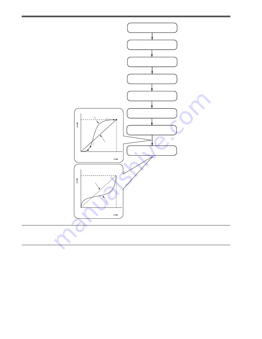
The machine uses the main controller to execute gradation correction to enable ideal gradation characteristics.
1. Start-Up Timing
- when the drum unit is replaced with a new one
- during post-rotation executed every 1000 prints
- during execution of calibration (user mode)
2. Particulars of Control
In the presence of a specific condition, the main controller sends the patch data of individual colors (Y, M, C, Bk) to the DC controller, which in turn forms a patch
pattern of each color (Y, M, C, Bk) on the ITB. Thereafter, the DC controller uses the patch image sensor (UN14) to measure the patch pattern, and sends the result
back to the main controller, which executes gradation correction based on the data so that ideal halftone images may be obtained.
In this control, the machine also forms a reference patch for use by abridged D-half control, and stores the reference data for abridged D-half control collected from
UN14. (See Notes.)
The machine executes gradation correction for all colors, regardless of which drum unit may have been replaced.
Patch pattern formation
Patch reading
UN16
D-half correction table creation
(Y, M, C, Bk)
EX: PASCAL correction table for Y
Actual gradation
characteristics
Ideal gradation
characteristics
0
100
Density data(D-CON)
Data output(V-CON)
DC controller
Main controller
Density data output
100
Gradation characteristics
after correction
Ideal gradation
characteristics
0
100
Density data(D-CON)
Data output(V-CON)
100
Start-up
Patch pattern data output
Main controller
DC controller
Printing patch pattern data
(3 types) to paper
Reading the printed pattern
on reader unit
Y1
Y2
Y63Y64
Summary of Contents for iR C3380 series
Page 1: ...Aug 29 2006 Service Manual iR C3380 2880 Series...
Page 2: ......
Page 6: ......
Page 23: ...Chapter 1 Introduction...
Page 24: ......
Page 26: ......
Page 52: ......
Page 53: ...Chapter 2 Installation...
Page 54: ......
Page 127: ...Chapter 3 Basic Operation...
Page 128: ......
Page 130: ......
Page 136: ......
Page 137: ...Chapter 4 Main Controller...
Page 138: ......
Page 160: ......
Page 161: ...Chapter 5 Original Exposure System...
Page 162: ......
Page 188: ...Chapter 5 5 24 F 5 68 4 Remove the original sensor 2 hook 1 F 5 69...
Page 189: ...Chapter 6 Laser Exposure...
Page 190: ......
Page 192: ......
Page 206: ......
Page 207: ...Chapter 7 Image Formation...
Page 208: ......
Page 256: ......
Page 257: ...Chapter 8 Pickup Feeding System...
Page 258: ......
Page 262: ......
Page 303: ...Chapter 9 Fixing System...
Page 304: ......
Page 306: ......
Page 321: ...Chapter 10 Externals and Controls...
Page 322: ......
Page 326: ......
Page 336: ...Chapter 10 10 10 F 10 10 2 Remove the check mark from SNMP Status Enabled...
Page 337: ...Chapter 10 10 11 F 10 11...
Page 359: ...Chapter 11 MEAP...
Page 360: ......
Page 362: ......
Page 401: ...Chapter 12 RDS...
Page 402: ......
Page 404: ......
Page 411: ...Chapter 13 Maintenance and Inspection...
Page 412: ......
Page 414: ......
Page 416: ...Chapter 13 13 2 F 13 1 8 9 1 2 3 3 5 6 7 10 11 12 13 14 4...
Page 421: ...Chapter 14 Standards and Adjustments...
Page 422: ......
Page 424: ......
Page 431: ...Chapter 15 Correcting Faulty Images...
Page 432: ......
Page 434: ......
Page 459: ...Chapter 16 Self Diagnosis...
Page 460: ......
Page 462: ......
Page 481: ...Chapter 17 Service Mode...
Page 482: ......
Page 484: ......
Page 571: ...Chapter 18 Upgrading...
Page 572: ......
Page 574: ......
Page 603: ...Chapter 19 Service Tools...
Page 604: ......
Page 606: ......
Page 609: ...Aug 29 2006...
Page 610: ......


